2.1 Buttons and LEDs
2.1.1 Test button
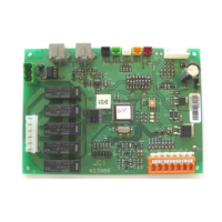
Situated on the main electronic board, it carries out different operations depending on how it is pressed:
• If it is kept pressed until the yellow LED is activated, certain timings are shortened and any fault
detected is reset.
• If it is kept pressed down until the red LED is activated, the optional accessories and probes connected
to the board are identified.
2.1.2 LEDs
There are three LED signalling diodes.
• The green LED indicates whether the unit is working properly or if there are incidents. If the unit is
working properly, this LED will flash at a constant frequency.
• The red LED indicates faults. If there are no faults, the LED remains switched off. It also lights up
when accessory configuration is being scanned.
• The yellow LED functions as a fault reset LED, and also indicates that a compressor timer is running
when it flashes.
In all the accessories:
• The green LED indicates whether there is communication and if it is correctly identified.
– If the LED remains lit, it indicates that the accessory is electrically powered but it has not been
correctly identified or it is not receiving the communications.
• The yellow LED:
– In the economiser accessory, it indicates that the outdoor air is favourable (LED lit up). The button
and the potentiometer store the renewal minimum.
– In the hot water coil accessory, it indicates that the water temperature is favourable (LED lit up)
or if the antifreeze function is being performed in the coil (LED flashing).
2
Buttons and LEDs
2.1 Buttons and LEDs
4
 Loading...


