MA5:5
V Range 502 l 652 l 802 Maintenance Manual
Johnston Sweepers Limited
Chapter - Pneumatic System
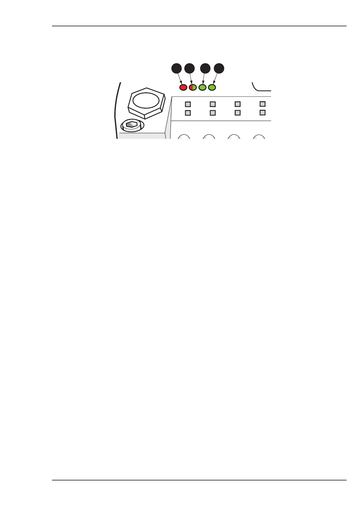
LED Status/Colour Indication
(1) Error (Red) Indicates the status of the CAN physical and indicates errors due to missing
CAN messages (SYNC, GUARD or HEARTBEAT).
(2) Run (Red/Green) Indicates the status of the CANopen network state machine.
(3) 5V (Green) Indicates when the Network power is connected to the Network connector,
indicating that the logic circuit of the module is powered.
(4) 24V (Green) Indicates when chassis voltage is applied to the power terminal of the supply
connector.
41 2 3
Pneumatic Valve Island - Status Indicators
Normal Operation
● Key on Chassis, JVM starts to boot up.
● VM10 LEDs
For 1-2 seconds after ignition on
Quick flashing of Red ‘Error’
Quick flashing of Green ‘Run’
Solid Green 5V
Solid Green 12/24V
After 2 seconds and until the JVM shows the clock page
Red ‘Error’ goes off
Slow flashing of Green ‘Run’
Solid Green 5V
Solid Green 12/24V
Once JVM shows the clock page
Red ‘Error’ remains off
Solid Green ‘Run’
Solid Green 5V
Solid Green 12/24V
● VM10 will then work correctly
See pages MA5:6 - 7 for sample fault situations.