3 Installation
3.3 Installing the remote display
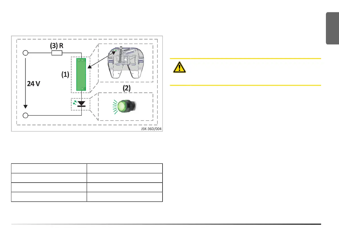
1 Sensor 3 Series resistor
2 Indicator light
Sensor (1) specifications
Max. switching voltage 200 V
Max. switching current 1.0 A
Max. switching capacity 20 VA
Stat. contact resistance 150 MOhm
1. Connect the indicator light (2) to the sensor (1).
Use Red and Black coloured wires (with ferrules).
2. Connect the series resistor (3) as shown in the diagram.
3. Connect the remote display circuit to the vehicle’s on-board
electrical system.
ATTENTION!
Reed switches may only switch ohmic loads (not relays,
coils, etc.).
EN
MUB 002 013 M30 (REV--) 02-2024 9