14
138344_Rev_D - C450 Kennebec 8.2.10
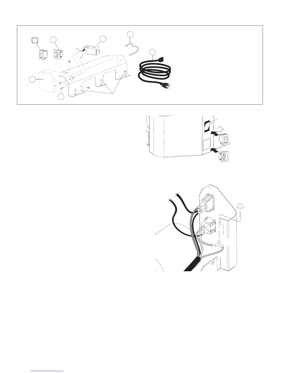
Figure 15. Wiring configuration.
B
BR
G
G
R
G
HI
OFF
LO
W
Switch
Power
Receptacle
Ground
Post
Blower Wire
Harness
BR
BR
Color Key
BR-Brown
R- Red
B- Black
W- White
G- Green
Blower Assembly
The blower is fully assembled, except for the wire
harness switch connections which depend on what
side you wish the power cord to be routed.
1. Remove the Blower Shroud to provide access to
the wire harness. Use a 10 mm socket or wrench
to remove the three M6 flange nuts that secure
the shroud to the base. See fig. 13.
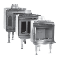
2. Insert Switch and Receptacle: Determine on
which side of the ash lip extension you wish to
install the power cord and switch. The snapstat
must also be installed on that side. Use a flat
head screwdriver and pliers to pry the knockouts
from that ashlip support. Work from the inside,
to avoid marring the outside surface. Insert the
Power Switch in the upper hole, and the Power
Cord Receptacle into the lower hole. See fig. 14.
3. Install Snapstat Extension Assembly: Remove the
snapstat knock-out from the appropriate side
of the Blower Shroud. Run the snapstat leads
through the hole and attach the bracket to the
Shroud using two #8 x 1/2” sheet metal screws.
See fig. 13.
4. Attach the Air Deflector: Using the two remaining
#8 sheet metal screws, attach the Air Deflector
to the Blower Shroud on the same side as the
snapstat is installed. See fig. 13, parts 4 and 5.
5. Connect the wire leads: Follow the diagram
as shown in fig. 15. Connect the loose wires as
follows:
Green: Remove an M6 nut from the corner post
and attach the ring terminals of the two ground
leads to that post. Attach the jumper lead to the
middle Power Receptacle terminal.
White: Wire harness to upper Power Receptacle.
Black: Wire harness to lower Switch terminal
Red: Wire harness to upper Switch terminal
Brown: • Snapstat to middle Switch terminal
• Snapstat to lower Power Receptacle
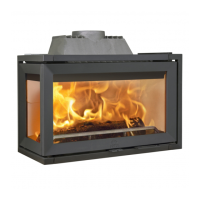
Figure 13. Blower hardware contents and assembly.
Hardware Bag Contents:
1. Power Switch
2. Power Cord Receptacle
3. Snapstat Extension Assembly
4. Air Deflector
5. #8 x 1/2” sheet metal screws, 4
6. Ground jumper wire
7. Power Cord
Tools Required:
• safety gloves and goggles
• 10 mm wrench or long socket
• 1/4” nut driver
• flat head screwdriver
• small pliers
8. Tuck the sheathed wire harness under the cutout at
the bottom of the Air Deflector.
9. Reattach the Blower Shroud to the Extension Base
using the three M6 x 12 flange head nuts
10. After attaching the Ashlip Extension / Blower As-
sembly to the fireplace (see below), plug the power
cord into the receptacle and run the cord to the
nearest house current outlet.
1
M6 Flange Nuts
Blower Shroud
6
7
3
2
4
5
Switch
Power
Receptacle
Figure 14.
Remove knock-outs and install inserts.
Knock-out
Ashlip
Extension
Support
 Loading...