15
138344_Rev_D - C450 Kennebec 8.2.10
Install the Ashlip Extension
Assembly
The assembly is comprised of a steel Extension Base
and a cast iron Ashlip plate. The procedure is the
same for double door and single door fireboxes.
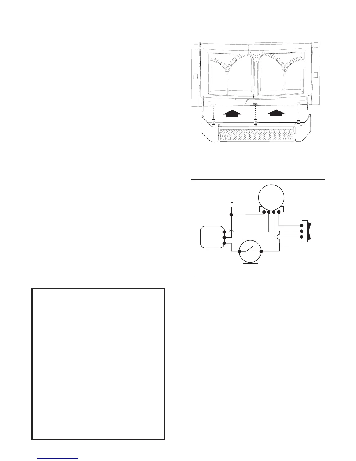
1. Engage the three spring clips on the Extension
Base with the adjoining cutouts on the firebox
base. Align the clips with these slots and push the
Extension to snap it together with the base of the
firebox base. The clips should slide over the front
edge of the bottom plate to engage with the
cutouts. See fig. 16.
2. The Ashlip plate simply rests on the Extension
Base. Engage the plate under the front doors.
3. Plug the power cord into place.
Figure 16. Attach the Ashlip Extenstion to the Firebox
base. Be sure that the clips slide OVER the front edge
of the bottom plate, not under it.
Blower Operation
The two-speed blower will enhance heat circulation
around the firebox and out into the room. The blow-
er is controlled by a heat activated switch (snapstat)
that will ONLY function when the control switch is in
either the HI or LOW setting. After the fire has been
burning for a time, the snapstat will react to the
heat and activate the blower, if the switch is in the
HI or LOW position. Conversely, the blower will con-
tinue to operate until the snapstat cools as the fire
wanes. The blower will then shut off automatically.
For best performance, do not turn the switch on
until after the fire is well-established.
If the blower is not needed, place the blower
control switch in the OFF position.
THIS BLOWER MUST BE ELECTRICALLY
GROUNDED IN ACCORDANCE WITH LOCAL
CODES OR, IN THE ABSENCE OF LOCAL
CODES, WITH THE CURRENT ANSI/NFPA 70,
NATIONAL ELECTRICAL CODE OR CSA C22.1-
CANADIAN ELECTRICAL CODE.
THIS UNIT IS SUPPLIED WITH A THREE-
PRONG (GROUNDING) PLUG FOR PRO-
TECTION AGAINST SHOCK HAZARD AND
SHOULD BE PLUGGED DIRECTLY INTO A
PROPERLY GROUNDED THREE-PRONG
RECEPTACLE. DO NOT CUT OR REMOVE THE
GROUNDING PRONG FROM THE PLUG.
ALWAYS DISCONNECT THE POWER SUPPLY
WHEN PERFORMING ANY SERVICE ON THE
FIREPLACE INSERT.
Figure 17. Blower Wiring Diagram
 Loading...