9
7. Remove the protective cover from the motor circuit board. Keep its fasteners nearby.
NEVER make electrical connections while the motor’s power supply is active. Disconnect the GFCI, RCD,
or circuit breaker before any wiring attempt.
8. If you will need to directly wire your power source into the motor’s circuit
board, connect your wires to the main power terminal, the only one
with three pin positions. Use a small athead screwdriver to loosen and
tighten the terminal screws as needed. Connect the ground wire to the
top PE pin, the live wire to the central L pin, and the return or neutral line
to the bottom N pin. Be sure no wiring is left bare and exposed.
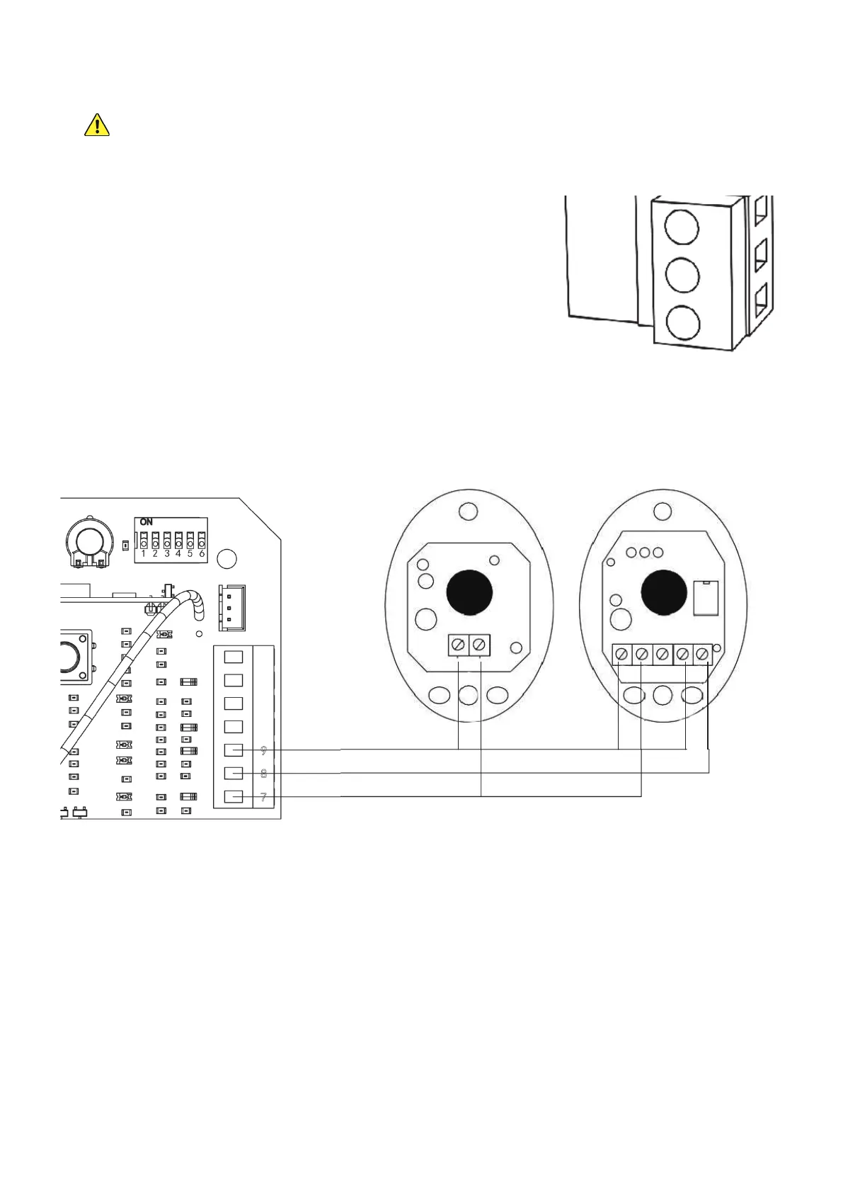
9. If you will be using the provided infrared sensors, nd the long terminal
next to the circuit board’s DIP switches. Remove the wire shorting pins 8
and 9 together. Connect the wiring from your infrared sensors as shown.
The sensors’ V+ pins should be connected to the bottom +15V pin (7);
the receiver’s NC pin should be connected to the central NC pin (8); and
the sensors’ V− pins and the receiver’s COM pin should all be connected
to the top GND pin (9).
10. Arrange the wiring for your motor as needed, being sure it will be protected from the moving gate. Use conduit,
silicone, or other sealant to minimise exposure to the elements and limit access by insects.
PE
L
N
Transmitter Receiver