8
Motor Installation
Using two people may make some parts of the following
process much easier.
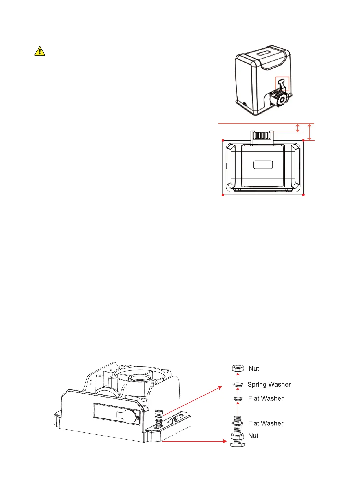
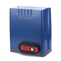
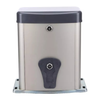
1. Remove the bolts on each side of the protective casing of the
motor (A). Remove the rubber grommet near the limit switch sensor
as shown and remove the casing from the motor. Use your release
key (B) to unlock the gear again.
2. Position the mounting plate (D) loosely onto the foundation bolts
(G) and position the motor loosely onto the mounting plate. You
can place two M10 nuts (N) between them now to approximate the
motor’s nal height or simply make the appropriate allowances in
the following steps.
3. Position one of the Module 4 racks (E) so that it rests on top of the
motor’s main gear. Move the rack so that it is positioned properly—
completely ush against the gate—while at the same time moving
the motor as well to keep its main gear positioned properly under
the rack’s teeth. Once both rack and motor are well positioned,
mark the locations on the gate and the foundation. It should match
the diagram at the right.
4. Hold both rack and motor in place while you manually move the
gate along its entire length. The gate should be so smooth and well
aligned that the rack slides along without a problem.
Correct any alignment or binding problem with the gate until the motor and rack can be held smoothly in place
and well aligned through the gate’s entire range of motion.
5. Once the gate is completely open, conrm that there will be at least 1 foot or 30 cm between the middle of
the main gear and the far end of the gate. This will allow enough room for the limit switch and help avoid any
possibility of accidental derailment. If necessary, move the gate opener over and then repeat the positioning
and alignment steps above.
6. Once the motor is fully correctly positioned, mark everything before removing the piece of track and the motor
itself. You can hold the motor in place using only the foundation bolts and nuts—with or without the mounting
plate—but it is recommended you use the mounting plate, the foundation bolts and nuts, and the M10×50 hex
bolts (I). The additional components, along with their at (L) and spring washers (M), should give your motor a
rmer hold and give you more exibility to carefully adjust its height and keep everything completely level.
The recommended arrangement is shown below, but add or remove washers and make other adjustments as
needed so that everything is completely level, well aligned, and rmly held in place once you’re done.
A
A
17–21 mm (0.7–0.8 in.)
B
53–57 mm (2.1–2.2 in.)
B