11
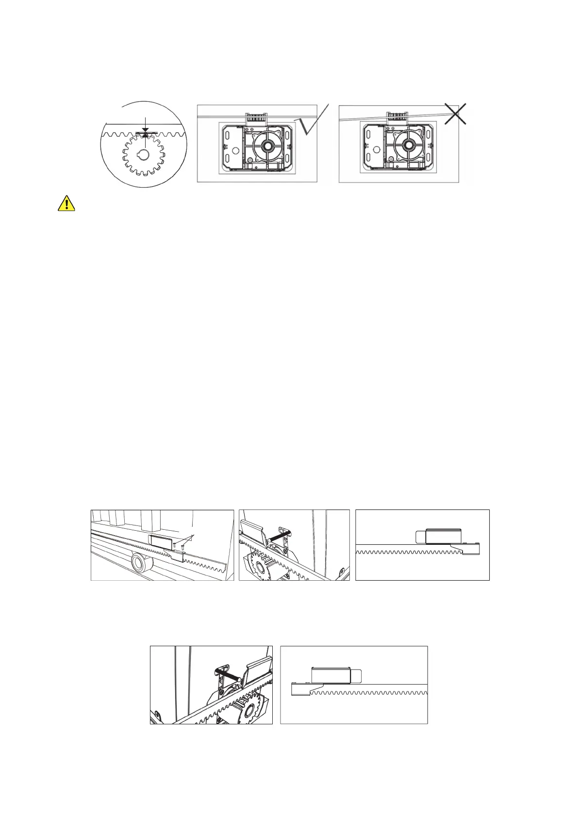
3. Unlock your main gear with your release key and move the gate back and forth. The gear should turn freely
without binding along the entire length of the rack. The rack should remain in the same perfectly straight line
over the gear from one end to the other, and there should be a space of about 1–2 mm (40–80 mil) between the
gear and the rack along its entire length.
1–2 mm
(0.04–0.08 in.)
AT NO POINT should the main gear directly support the weight of the gate.
If the placement of any rack causes the gear to directly support the weight of the gate, this WILL cause
malfunctions, premature failure, and void any warranty stated or implied. Loosen the screw, adjust the bracket
around it, adjust any other parts of the racks to maintain alignment, and tighten everything back into place.
4. Repeat the same process, testing, and adjustment with the next length of rack. Slot it into place beside the rst,
support it using the mounting lugs and self-tapping screws, and adjust it as needed to keep everything level
and smooth without forcing the main gear to directly bear the weight of the gate. Repeat this for the rest of the
racks, conrming each time that the small gap between the rack and the gear’s teeth is evenly maintained.
5. If the nal position of the racks leaves dangerous or unsightly excess length sticking out either side of your
gate, fully tighten the screws supporting all of its brackets and then remove the excess length with a hacksaw,
angle grinder, or similar tool.
6. If any brackets were left unsupported as you went, close the gate back and add the additional lugs and self-
tapping screws. Continue checking the gear’s placement and making any necessary adjustments as you go.
Limit Switch Installation
1. The two limit switches (F) are designed to attach to the rack, signaling to the motor when to stop in either
direction. They should work in conjunction with your gate’s end stops and brackets to automatically bring the
gate to a gentle stop at the exact best position every time. Neither the limit switches nor the end stops and
brackets should be used without the other.
2. To position the close limit switch, roll the gate to its completely closed position and then roll it back open about
15–20 cm (6–7¾ inches). This will give your gate space to come to a more gentle stop once the limit activates.
3. Fit the limit switch onto the rack as shown, positioning it beside the motor’s spring-mounted limit detector and
tightening it into place with two M6×10 bolts (H).
4. Repeat the process on the other side. Roll the gate to its completely open position and then roll it back closed
about 15–20 cm (6–7¾ inches) to provide space for it to roll to a stop ahead of your end stops and brackets.
Fit the limit switch onto the rack as shown, positioning it beside the motor’s spring-mounted limit detector and
tightening it into place with two M6×10 bolts.
5. Roll the gate from one end to the other, conrming that there is a small audible click when the limit detector is
bent by each of the limit switches. Use the manual release key to lock the motor back into standard operation.
6. If you have not already done so, mount the infrared sensors and fully connect and bind their wiring.
M6×10 Bolts
Closed Position Limit Switch
(Reverse for Left Side Use)
Open Position Limit Switch
(Reverse for Left Side Use)