6
6. Provide a stable, compatible, and well-grounded power connection for the gate opener. The motor’s outlet
should be within sight of the gate, protected from the elements, and equipped with a GFCI, RCD, or circuit
breaker. It should be at least 1 m (3 ft.) high to minimise damage from weather. If possible, place the outlet
higher than 5 feet or 1.5 m to limit access by children and animals.
It is recommended that any wiring near the gate run underground inside PVC pipe or conduit to minimise any
possibility of tripping or accidental damage. The wiring for the outlet or power connection should be a 3-core
cable at least 1.5 mm² (16 AWG) thick. If your gate’s position is further than 90 m (300 ft.) from the nearest
power source, the wire should be at least 2.5 mm² (14 AWG) thick. At distances beyond 300 m (1000 ft.), a
professional electrician should be consulted to safely deal with the expected voltage drop.
7. When properly congured and activated, the gate opener’s collision reaction system
functions as a Type A entrapment protection and an attentive user and the device
remote function together as a Type B1 non-contact sensor. Users should also install
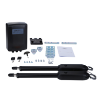
the provided infrared sensors, especially if any additional access method is added.
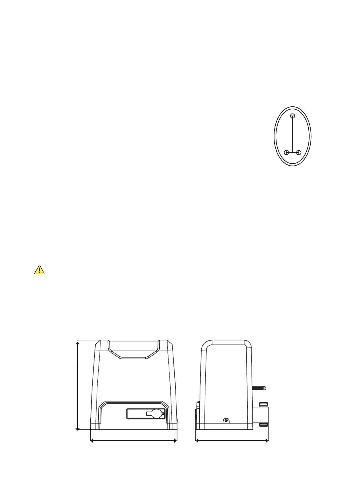
To use the infrared sensors, prepare locations for them on opposite sides of your
gate. They should be directly across from one another at least 2 m (6′7″) apart but no
further apart than 20 m (65 feet). If possible, they should be placed where they will be
shielded from direct sunlight. Pilot holes for their support bolts (not included) should be
placed as shown.
Each sensor will need a connection to the circuit board and a source of 12V DC power. This can be provided
from the motor circuit board’s +15V pin (7) or separately. The signal line from the receiver—the sensor with a
5-pin terminal—and any power lines should be prepared ahead of time. Additional wires should be at least
0.5 mm² (22 AWG) thick. If possible, these lines and those from any other control or access system should also
be placed underground inside a PVC pipe or conduit separate from the one used for the motor's power cord.
Again, all wiring connections should be insulated and protected to withstand rain and inclement weather.
Base Installation
Your motor MUST be rmly secured for safe use. Do not attempt to use it loose or only secured to thin
pavement.
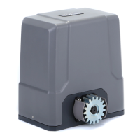
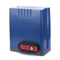
1. Prepare a suitable location for the motor (A) beside either end of your gate. The default settings are for placement
on the right side of your gate when facing out from your property. It can be installed on the left side but some
settings will need to be reversed for some functions like automatic closure to work properly.
2. The motor itself will need an area of 27.1×22.8 cm (10.7×9 inches).
28 cm (11 in.)
27.1 cm (10.7 in.)
22.8 cm (9 in.)
4.5 cm
1.77 in.
2 cm
0.79 in.