7
3. If the area beside your gate already has concrete at least 25 cm (10 in.) thick, you can attempt to secure the
gate opener to it with a drill and suitable fasteners (not included). Simply nd the right position for the mounting
plate and use it to mark the locations for your anchor bolts.
If the area beside your gate is covered with earth or thin pavement, you will need to create a concrete platform
to fully anchor the motor. Dig a hole about 50 cm long, 35 cm wide, and 20 cm deep (20×14×8 inches). Prepare
a form box with the same dimensions and t it into the hole. Nonstick spray can be used to minimise moisture
absorption and ease its future removal.
4. Fill the form with concrete. You will need a minimum of 35 L (0.035 m³ or 1.25 cu. ft.) of concrete, equivalent to
a bit more than four standard 25 kg bags. Aim for at least a 4000 psi or C30 strength mix. A metal wire or cage
frame can be added near the sides to further shape and reinforce your concrete foundation.
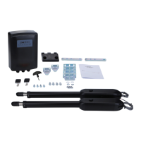
5. While the concrete is still wet, adjust the cables’
PVC pipes as needed and insert the four
M10 foundation bolts (G) as shown. Use the
mounting plate to conrm that they are properly
positioned and aligned, remembering to leave
the correct distance from the future location
of the motor to the gate. For best results, coat
the foundation bolts in a protective solution to
minimise corrosion during their time in the wet
concrete and afterward.
Alternatively, you can simply create a solid
foundation, position the motor and wiring as
needed once it dries, and then use your drill and
suitable fasteners to anchor the motor to the
concrete.
6. Carefully level the upper surface of the concrete.
7. Wait at least 24 hours for the concrete to set, protecting the area from any rain or other weather as needed.
8. Remove the form box from around the concrete. Pack the surrounding soil tightly back into place to hold the
new foundation. Adjust the concrete and surrounding dirt as needed to ensure it is snuggly t, rmly positioned,
and completely level.
If you ever subsequently notice the gate opener rocking with the concrete during use, add additional
concrete or further secure the base as needed.
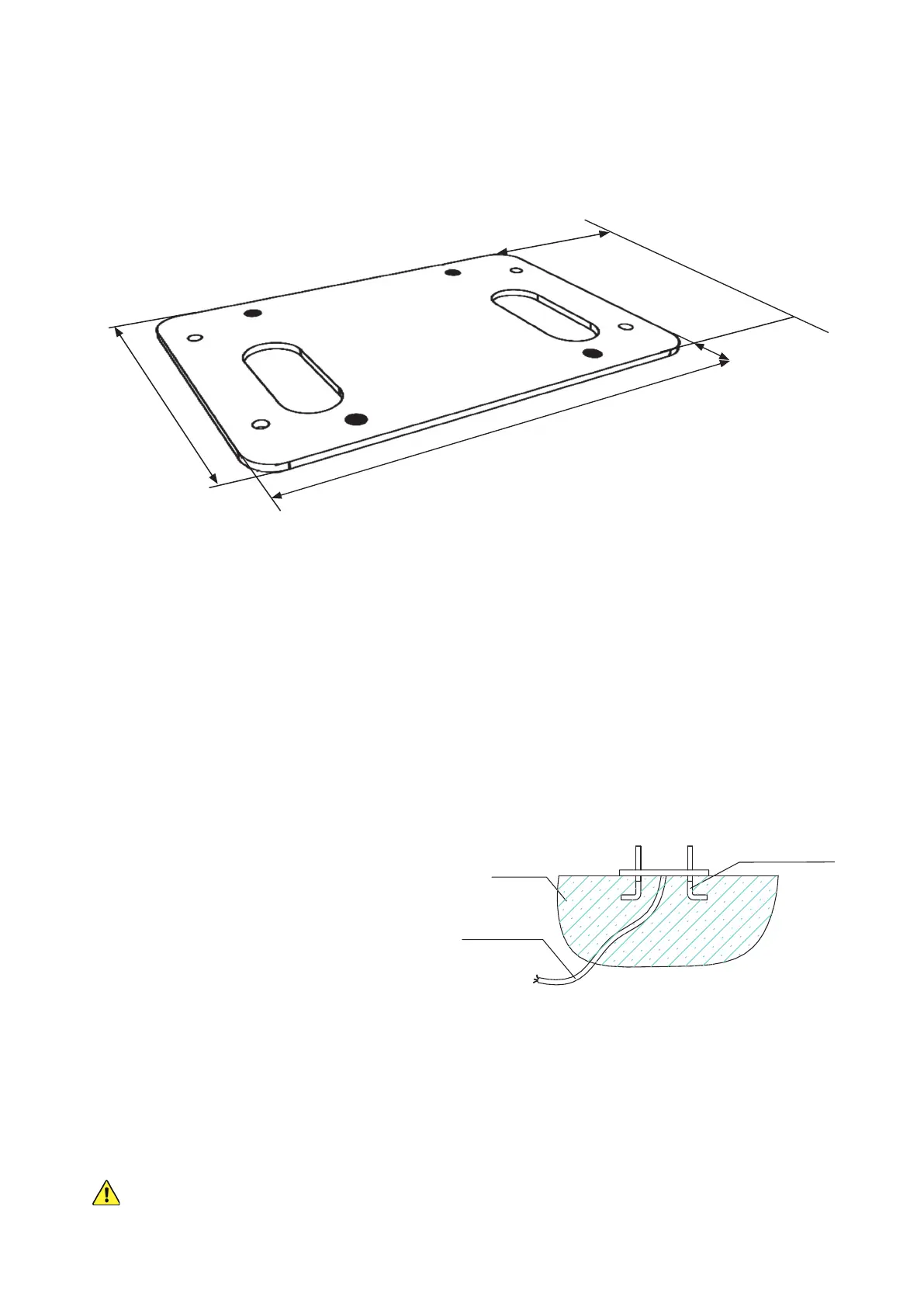
The outer edge of the gear will need to be positioned almost exactly 19 mm (¾″) from the nearest part of the
gate. The mounting plate (D) can be used to more easily check and mark initial placement, but its outer edge will
need to be positioned 5.5 cm (2⅛″) from the nearest part of the gate to adjust for the width of the gear itself. The
middle of the plate should be set at least 30 cm (1 ft.) from the nearest end of the gate to allow enough space on
the track for the limit switches and to avoid any possibility of derailment.
Foundation Bolt
Concrete
Power Line
17.7 cm
7 in.
27 cm
10.6 in.
5.5 cm
2.1 in.
30.5 cm
12 in.