10
Rack Installation
1. Before placing your racks, lay them out in position along the entire length of the gate where they will need to
be installed. Check that both ends have at least 30 cm (1 ft.) beyond the expected position of the main gear
for their limit switch and ensure that you will not end up with a small piece of a rack at the end that is only
supported by a single brace.
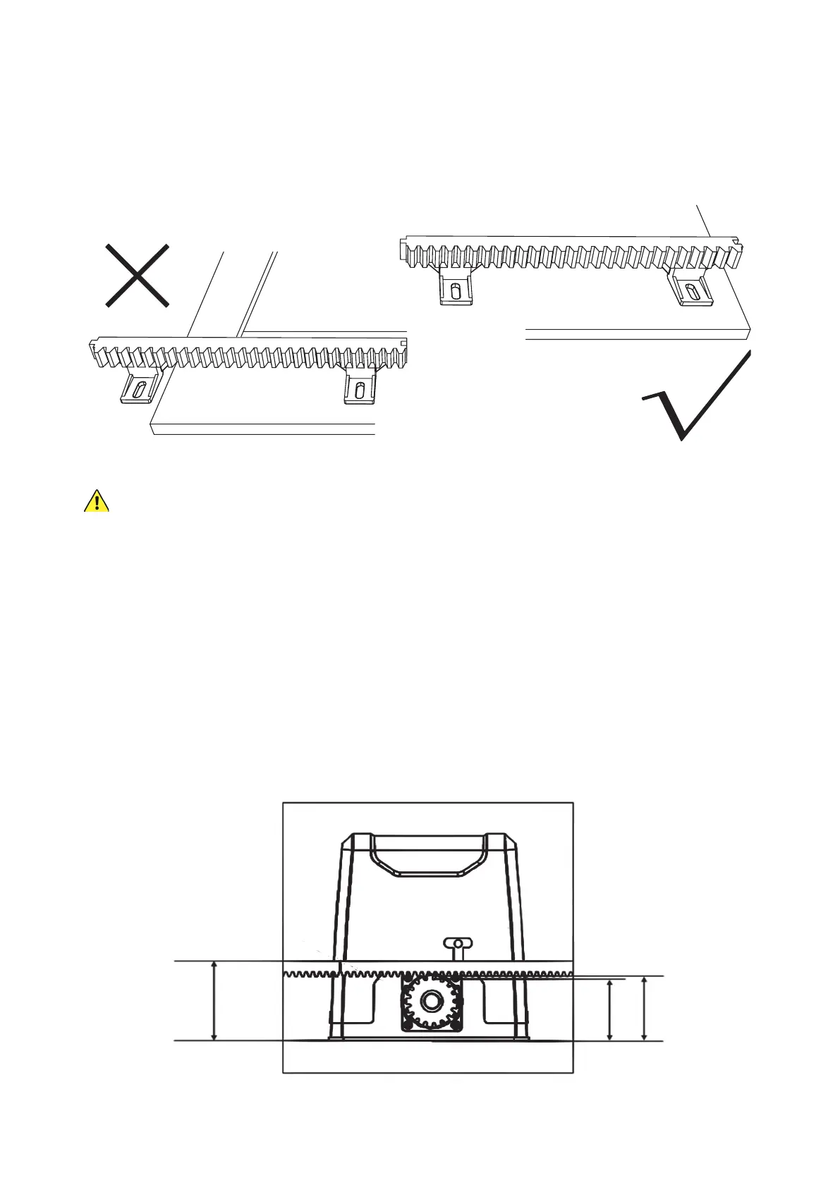
All of the gate racks you install MUST be supported by at least TWO separate braces to remain securely
held and properly aligned over time.
If you
do
end up with too little of a rack at the end, the best solution is to scoot all of the racks over together, so
that enough space is created by moving the rst that both braces on the last rack now t onto your gate. If this
is impossible, you can purchase a shorter or longer compatible Module 4 rack that will allow proper placement
of the other pieces or simply use one fewer rack and move the gate less far out of the way.
Mark the nal arrangement as needed.
2. Slide the gate nearly closed and position the rst piece of the rack just above the motor’s main gear. It may help
to lock the main gear back into normal operation, holding it tight. Once the rack is precisely positioned, screw
one of the mounting lugs (K) and self-tapping screws (J) into the nearest support bracket on the far side of the
motor opposite your entrance. For best results, use an impact driver. Next, put another lug and another self-
tapping screw into a support bracket on the near side of the rack closer to your entrance. The distances should
almost exactly match those in this diagram:
113 mm
(4.9 in.)
83 mm
(3.3 in.)
93 mm
(3.7 in.)