5
Press the button again to stop the gear. Press the button a third time to start the motor again in reverse. This
should cause the gear to begin turning clockwise, which closes gates from the right. Press the button a fourth
time to stop it again. Finally, start the gear turning either direction and then carefully but rmly bend the limit
detector spring. Conrm the wheel stops and then unplug the motor.
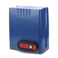
Keep the motor and other devices FULLY disconnected from power for the rest of installation, except as
instructed for testing operation.
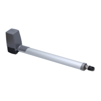
3. Double check your gate’s weight and size. Conrm that your gate opener will be able to provide the necessary
torque for safe and consistent operation. Conrm that your gate does not exceed 12.2 m (40 ft.) in length. Check
how far your gate will need to move to open and close as needed. If your gate will need to move more than 4 m
(13 ft.), you will need to purchase additional Module 4 racks and connect them with those already provided with
your device. Be sure any additional track is completely identical and ush with the rest.
NEVER use weak or incompatible track with this device and ALWAYS ensure the track is securely
fastened and completely ush prior to any use.
4. Double check your gate’s condition. Conrm that it is properly installed on rm and level ground entirely within
your own property. Conrm that it moves smoothly and remains completely plumb and level both vertically and
horizontally along its entire path. Its wheels and guides should rotate easily and be free of any corrosion, dirt, or
grime. Any track should be cleaned and rmly mounted along its entire length. There should be adequate space
at both ends to avoid any pinching or crushing hazard once movement is automated.
If it is impossible to eliminate hazardous areas around your gate, each one should be blocked o and
clear warnings posted.
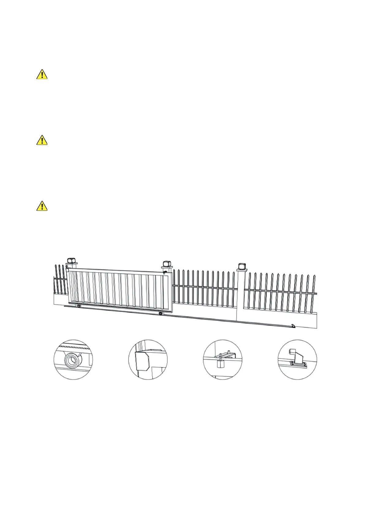
Conrm that your gate includes all of the following features or their equivalent. In particular, be sure it will be
able to rmly mount the Module 4 rack and that end catches and stops on both sides are prepared so your gate
can never roll o its designated path.
Track and Wheels End Catch Guide Rollers End Stop
For best results, place one or more warning signs so that they are clearly visible to anyone near the gate on
either side. Such signs should warn of the possibility of serious injury or death from the moving gate, warn
against allowing children nearby, and guide pedestrians to keep clear and use a separate entrance. As potential
pinch points, access to exposed wheels must also be restricted using roller guards. Similarly, the gate and
nearby fence or wall must be constructed so that they do not provide ANY openings below a height of 1.2 m (4
ft.) above the ground where a 5.8 cm (2¼″) diameter sphere would be able to pass through.
5. Provide a separate gate for pedestrians if needed. Once automated, the main gate should ONLY be used for
vehicular trac. Be sure the pedestrian access is clearly visible or clearly marked from the area of the gate, but
it should be located safely away from the main gate’s range of motion.