Do you have a question about the JRC JFC-7050 and is the answer not in the manual?
Explanation of safety symbols used in the manual for warnings and instructions.
Safety instructions specifically for system operators regarding usage and hazards.
Precautions to follow during the installation process to avoid injury or malfunction.
Safety precautions for internal inspection and maintenance procedures.
Important operational guidelines to prevent system failure or deterioration.
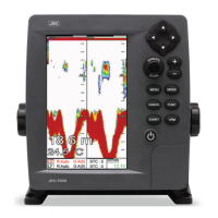
Introduction to the JFC-7050 Echo Sounder/Fish Finder and its capabilities.
Details on the JFC-7050's features and the standard equipment configuration list.
Description of the functions of each key on the JFC-7050 keypad.
Guide on how to use power, brightness, frequency selection, and gain/STC controls.
Description of the front and rear views of the JFC-7050 display unit.
Details on the specifications and pin assignments for the transducer and power/IO connectors.
Explanation of the main screen layout, including high and low frequency displays.
Description of the highway display providing a 3D view of progress toward a destination.
Information on the steering display showing ship's speed, course, bearing, and TTG.
Guide to selecting echo sounder modes like Normal, Bottom Zoom, and Bottom Lock.
Instructions on setting the gain level for optimal echo sounder performance.
Procedure for selecting and displaying different pages or screen layouts.
Steps to customize the formation and layout of the screen displays.
Guide to editing and customizing the data bar information displayed on the screen.
Instructions on editing navigation data that appears on the display.
Explanation of depth range measurement and shift function for detailed bottom viewing.
Settings for A-scope, image speed, white line, and bottom zoom range.
Configuration options for depth, temperature, and speed display and font size.
Settings for interference and noise rejection to improve signal clarity.
Options for adjusting screen color, pulse, and output power levels.
Configuration for depth, temperature, and fish school alarms.
System setup, unit selection for distance, depth, and temperature.
Settings for time, date formats, and NMEA input/output sentences.
Configuration for speed source, boat speed correction, and fishing mode.
Setup for FUNC/EVENT keys, Waypoint management, recording, and screen capture.
How to use the movable marker for measuring depth and target distance.
Guidance on selecting a location and installing the display unit.
Instructions for connecting the power supply and various sensors.
Overview of transducer installation types (transom and through-hull) and considerations.
Guidelines for mounting transom transducers and their maintenance.
Information on selecting and installing through-hull transducers.
How hull dead-rise affects transducer mounting and the use of fairing blocks.
Maintenance advice for through-hull transducers, including antifouling paint.
Details of the one-year guarantee period for the main unit and accessories.
Conditions and reasons for service that are not covered under the guarantee.
| Brand | JRC |
|---|---|
| Model | JFC-7050 |
| Category | Marine Equipment |
| Language | English |