Procedure sheet to change ROM IC page 1 of 3
Procedure
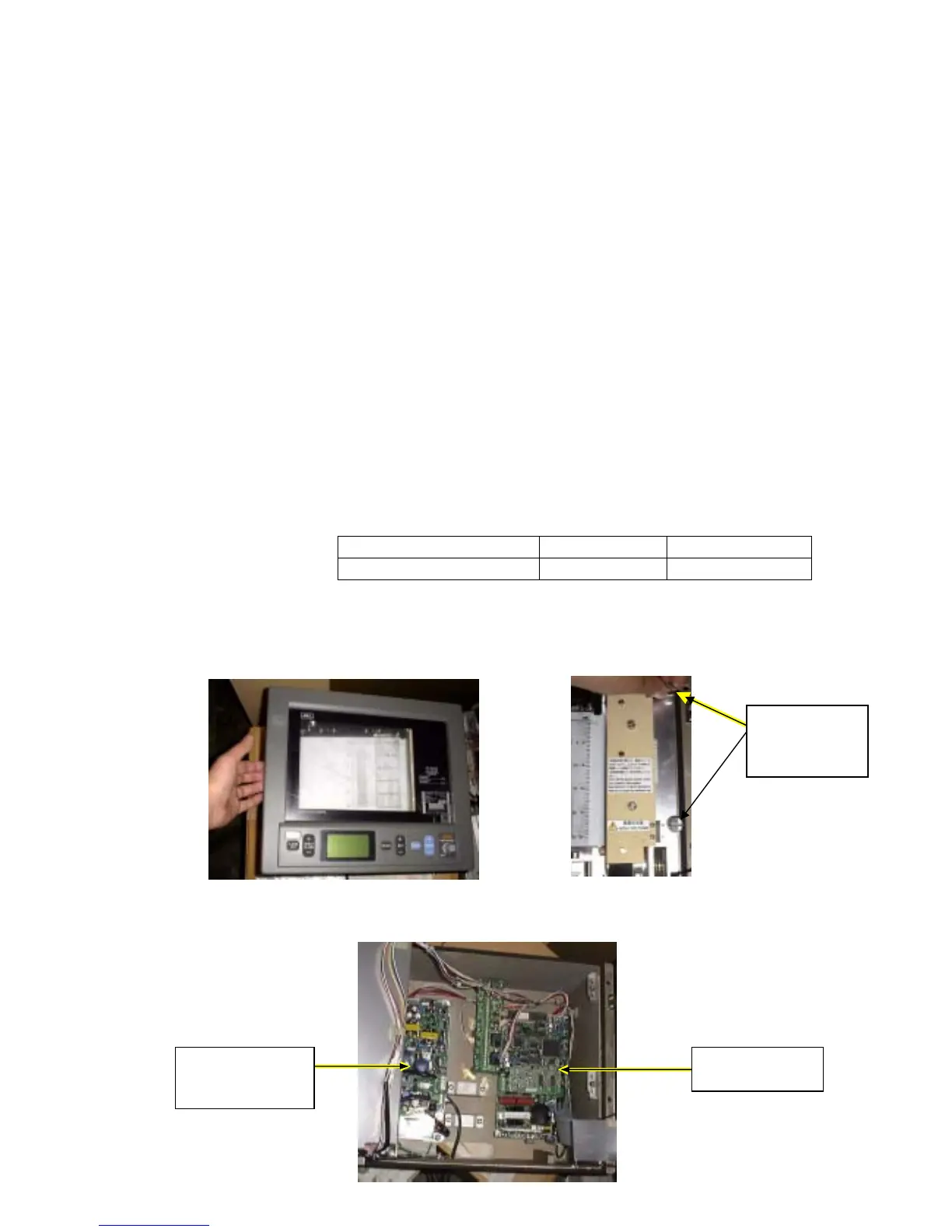
1. Open the front panel of echo sounder and mechanical block. (photo. 1, 2)
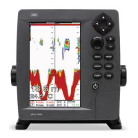
2. Turn off the main switch on the power supply unit. (photo. 4)
3. Remove the ROM IC (version CO-R1.02) on the TX/RX unit. (photo. 5)
4. Insert the modified ROM IC: version CO-R1.02SP0. (photo. 6)
5. Turn on the main switch. (photo. 7)
6. Close the mechanical block and front panel of echo sounder. (photo. 8)
7. Turn on the power switch on the front panel.
8. Verify the LCD display on the front panel. (photo. 9)
Verifying point
1. When start to work, buzzer will sound four and half times.
2. During the sounds, LCD will display opening massage with ROM
version. The displayed ROM version should be “CO-R1.02SP0”.
If no buzzer sounding or no LCD displaying, ROM would not be
inserted correctly. Please confirm IC’s direction and lead bending.
[Reference] TX voltage with TX dummy(8000pF 250 ohm)
CO-R1.02 CO-R1.02SP0
TX voltage Vp-p 1250V 700V
Photographs
Photo. 1 Open the front panel Photo. 2 Open the mechanical
Section
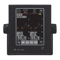
Photo. 3 Flame section
Screw two
screws
Power supply
unit
TX/RX unit