3-17
1.2) Procedure for not using a dedicated cable
When receiving azimuth information data from the GPS compass, connect the necessary signal lines to
the attached NMEA data connector P5 (for J5) LTWBD8BFFA-LL7001 using the following diagram as
the reference.
Signal name GPS compass connector side JMA-5200MK2 side
Compass data input + Disconnected Disconnected
Compass data input - Disconnected Disconnected
Compass data output + RADAR-4 (3) NSKRX +
Compass data output - RADAR-3 (4) NSKRX -
GND Disconnected Disconnected
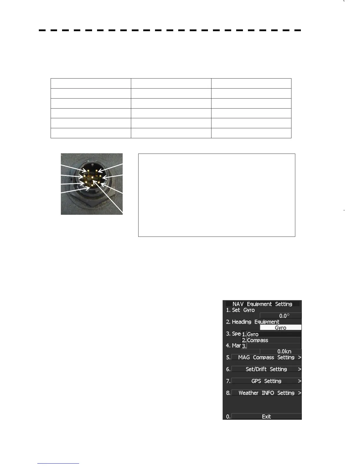
Connector for GPS compass/NSK equipment (J5)
To GPS compass or NSK unit
(1) NSKTX- : Output of receiving signals from NSK+
(2) NSKTX+ : Output of receiving signals from NSK-
(3) NSKRX+ : Input of receiving signals from NSK+
(4) NSKRX- : Input of receiving signals from NSK-
(5) GND : Power GND for NSK
(6) ALM+ : Dry contact output 1
(7) ALM- : Dry contact output 2
(8) +5V : Power for NSK (+5V)
The above-mentioned connections are available only for receiving bearing data from JLR-10. About how
to receive position information, refer to section 3.6.
2) Setting the GPS Compass (JLR-10)
Set the following information with the GPS compass.
Data output format=NSK
Refer to the manual for the GPS compass for the detailed setting method.
3) Setting the JMA-5200MK2
3.1) Heading Equipment Setting
1) Press and hold [RADAR MENU] key.
The CODE INPUT Menu will appear.
2) Enter [0] and press the [ENT] key.
The Adjust Menu will appear.
3) Press [6] key.
Press [2] key.
The Heading Equipment Setting Menu will appear.
4) 1. Set the gyro.
3.2) Baud Rate Setting
When setting the gyro in 3.1) Heading Equipment Setting, the
setting of the baud rate is not required.
(1)
(2)
(3)
(4)
(7)
(6)
(5)
(8)
 Loading...


