3-45
(7) Securely mount the terminal board, which has been removed in procedure 1, to the processing unit, pull
the "P4311" labeled end of the cable (H-7ZCRD0908) attached to the AIS interface as shown in the
following photograph, and connect the to the terminal board's connector J4311.
(8) Attach the processing unit cabinet cover and complete the installation of the plotter circuit.
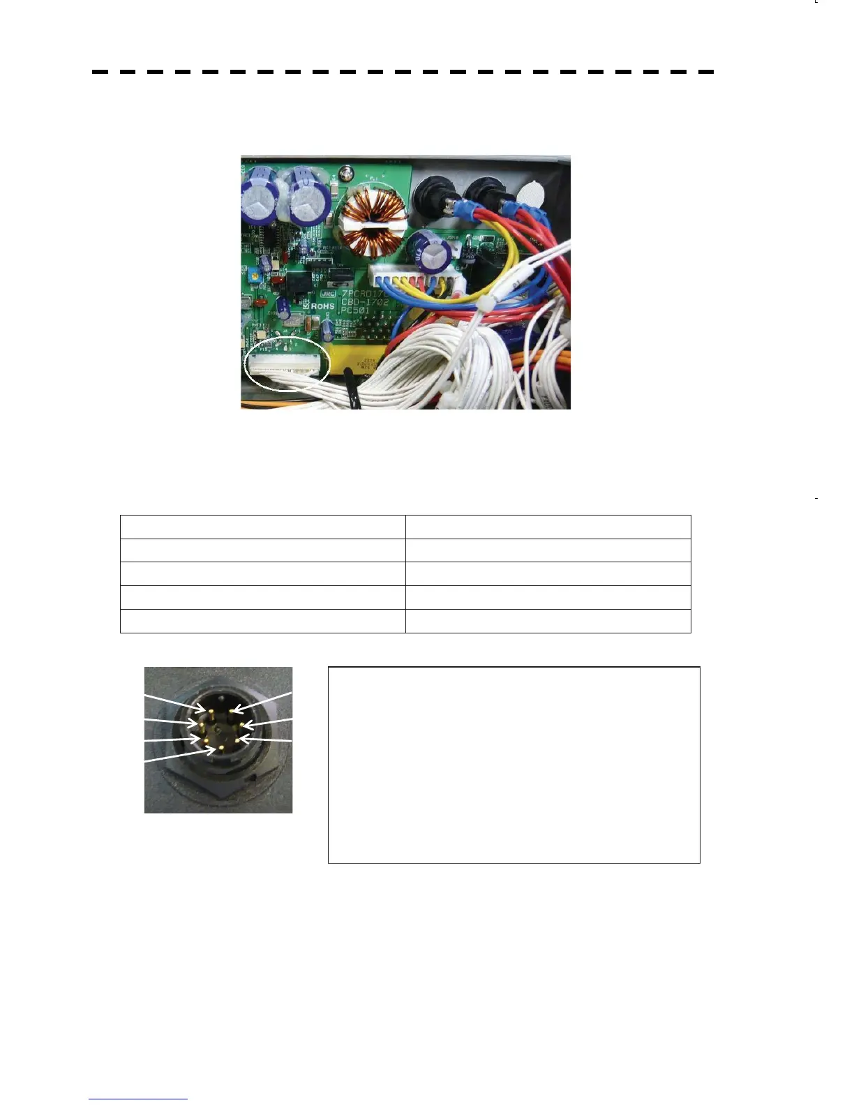
1.2) Connection with the NMEA device
When connecting AIS and this radar, connect the necessary signal line to the attached NMEA data
connector P6 (for J6) LTWBD7BFFA-LL7001 using the following diagram as the reference.
JMA-5200MK2 side AIS device side
(1) NMEA RXD + Data output + from the AIS
(2) NMEA RXD - Data output - from the AIS
(3) NMEA TXD + Data input + to the AIS
(4) NMEA TXD - Data input - to the AIS
Connector for AIS compass or NMEA equipment (J6) RS-422
To AIS or other NMEA device
(1) NMEA RXD㧗 㧦NMEA input 㧗
(2) NMEA RXD㧙 㧦NMEA input 㧙
(3) NMEA TXD㧗 㧦NMEA output 㧗
(4) NMEA TXD㧙 㧦NMEA output 㧙
(5) GND 㧦GND
(6) EVENT㧗 㧦Dry contact input 1
(7) EVENT㧙 㧦Dry contact input 2
2) Setting AIS
Set the following information in AIS.
Data output format NMEA V2.0 OR LATER VERSION
Baud rate 38400bps
Output sentence $xxVDM AIS VHF data-link message
$xxVDO AIS VHF Data-link Own-vessel report
(1)
(2)
(3)
(4)
(7)
(6)
(5)
 Loading...


