6-1
6.1 INSPECTION AFTER INSTALLATION
After installation has been completed, it is necessary to inspect whether all of the procedures have been done
properly. Specifically, inspect whether cable connections are correct, each device has been mounted securely,
water has not leaked onto the scanner (fastening of cable grand, cover, etc.), and whether the cable's shield
meshwork has been properly installed.
6.2 OPERATION INSPECTION
After confirming that the equipment has been properly installed, carefully read the instruction manual and be
fully aware of the operation procedures before inspecting radar operations. Make sure that the ship's mains'
voltage is within the allowable range and then operate the radar according to the instruction manual. Then,
make sure that there are no abnormalities, and operate all of the functions to check that they operate normally.
If, for some reason, the monitor, PCB, or unit needs to be replaced, refer to the attached procedures for
removing those devices. After the replacement has been completed, make sure that screws have been tightly
fastened and all of the connectors have been connected, and then turn on the power and conduct inspection.
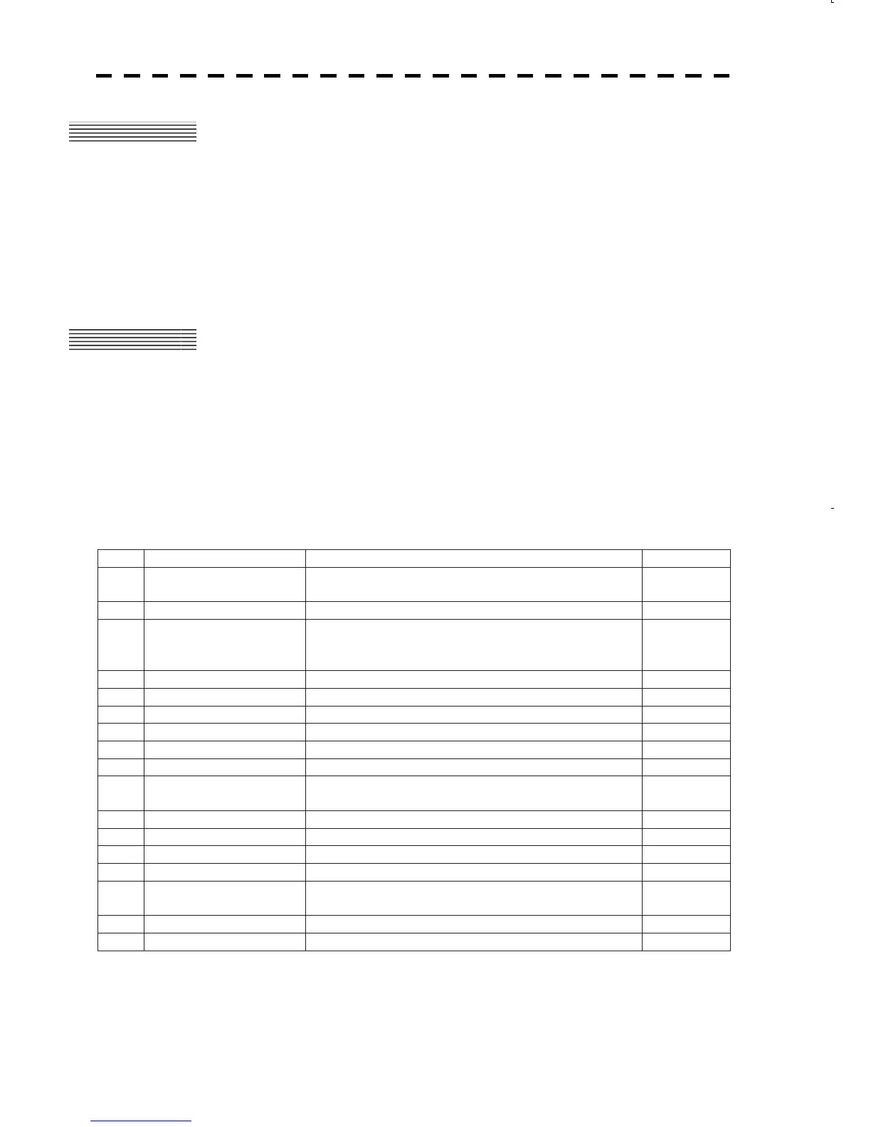
Inspection Checklist
No.
Items Contents OK or NG
1
Tune adjustment
Manual tune mode and automatic tune mode is normal
operated
2
Bearing adjustment Within r1q of the true value
3
Range adjustment
Displays the true value of distance for a target of
which range is already known in 0.25NM observation
range
4
Antenna height Set to true value
5
Set true bearing Following the bearing device (GYRO etc...)
6
Set ship's speed device True value is indicated
7
GPS GPS signal is normal received
8
Target Tracking / EPA Normal performance
9
AIS Normal display
10
Performance monitor
Normal performance
Default value is described in information label
11
Interswitch Normal performance for settings straight or not
12
Error message Error message is not displayed
13
Magnetron current Displays the normal value
14
Fuse Specified fuse is used
15
False echoes
If false echo is appeared when cause and action are
explained for user
16
Display of monitor Normal displayed
17
Self test Normal performance in all contents

 Loading...


