3-29
2. Connect the speed log signal input line to TB20. To do so, for the pulse type, connect the line to the
PULSE side and, for the synchro type, connect the line to the SYNC side. With respect to the positive (+)
and negative (-) sides, when the pulse type is selected, the negative (-) side is the ground.
3) Setting the JMA-5200MK2
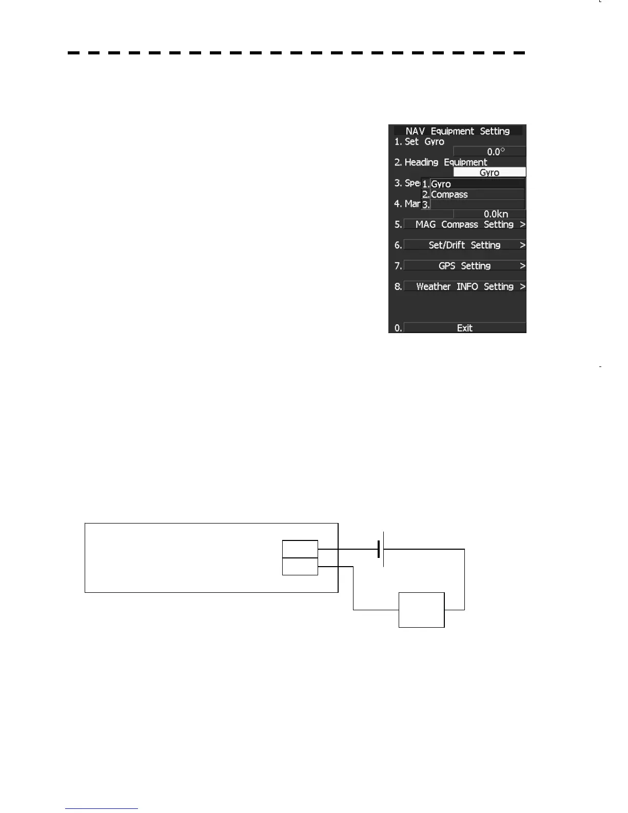
3.1) Heading Equipment Setting
1) Press and hold [RADAR MENU] key.
The CODE INPUT Menu will appear.
2) Enter [0] and press the [ENT] key.
The Adjust Menu will appear.
3) Press [6] key.
Press [2] key.
The Heading Equipment Setting Menu will appear.
4) 1. Set the gyro.
3.2) Baud Rate Setting
When setting the gyro in 3.1) Heading Equipment Setting, the setting of the baud rate is not required.
4) Connections to an external buzzer
When connecting an external buzzer to the NSK unit, read the following guideline.
TB40 of the built-in PCB CSC-631 has a dry contact output, so that if the connection "TB-40 Power
Supply Positive terminal of the buzzer Negative terminal of the buzzer Power supply ground"
is made, then a buzzer can be sounded when there is an alarm from the JMA-5200MK2.
Refer to “3.21 CONNECTING TO EXTERNAL BUZZERS” for connection of external buzzers and set
the following information for the connection of external buzzers.
2) Jumper setting
3) Contact operation setting
Connection Example
CSC-631
TB40
Buzzer
Batter

 Loading...


