Be sure to observe the following to protect against a re, electrical shock, injury or damaged components.
* Be sure to unplug the machine before disassembly, assembly or adjustment of the machine.
* Be sure to carefully prevent electric cords from being caught, coated surfaces from being damaged
as well as wrong wiring during assembly.
* Be sure to use the proper genuine parts when changing any of the machine parts.
CAUTION:
CONTENTS
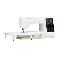
[1] Specications of HZL-UX8 ........................................................................................ 1
[2] Search by trouble (related to mechanical components) ........................................ 3
[3] Principal parts ............................................................................................................ 4
[4] Disassembling the machine covers ......................................................................... 5
[5] PCB connection diagram ........................................................................................ 12
[6] Adjustment ............................................................................................................... 16
6-1 Adjusting the needle bar height ...................................................................... 16
6-2 Adjusting the needle entry point ..................................................................... 17
6-3 Feed dog height ................................................................................................ 18
6-4 Timing belt ........................................................................................................ 19
6-5 Feed timing ....................................................................................................... 19
6-6 Adjusting the shield ......................................................................................... 20
6-7
Hook driving shaft coupling and the lateral timing of the hook driving shaft
.. 21
6-8 Timing between the needle and the hook ...................................................... 22
6-9 Clearance between the needle and the blade point of hook ........................ 23
6-10 Position of the hook rotation stopper plate ................................................. 25
6-11 Adjusting the bobbin thread tension ............................................................ 25
6-12 Adjusting the needle thread tension ............................................................. 26
6-13 Vertical position of the needle threading hook ............................................ 27
6-14 Adjusting the auxiliary hook height .............................................................. 28
6-15 Adjusting the opening amount of auxiliary hook ........................................ 29
6-16 Adjusting the presser bar height .................................................................. 29
6-17 Motor belt ........................................................................................................ 30
6-18 Longitudinal feed ............................................................................................ 31
6-19 Presser foot lifting .......................................................................................... 32
6-19-1 Position of the presser foot lifting motor ....................................................32
6-19-2 Adjusting the height of the auto-lifter ..........................................................33
6-20 Thread trimming ............................................................................................. 34
6-20-1 Attaching/removing the thread trimmer unit ...............................................34
6-20-2 Adjusting the thread trimming switch .........................................................35
6-21 Attaching/removing the top feed dog ........................................................... 36
6-22 Position of the automatic DF motor .............................................................. 37
6-23 Bobbin thread detection sensor ................................................................... 38
6-23-1 Attaching/removing the bobbin thread detection sensor ..........................38
6-23-2 Adjusting the bobbin thread detection sensor ...........................................39
6-24 Service mode .................................................................................................. 40
6-24-1 Service mode screen .....................................................................................40
6-24-2 Service-mode items and descriptions .........................................................40
 Loading...