– 5 –
Secure the wiring from the machine head with cable
clip band
which is assembled onto the pedal
sensor.
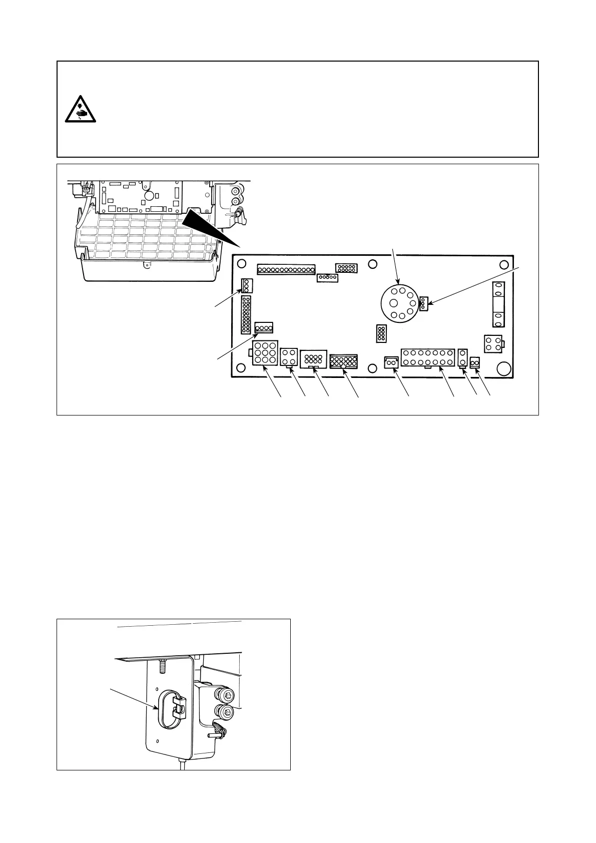
7.
Connecting the cords
WARNING :
• To prevent personal injury caused by abrupt start of the sewing machine, carry out the work after
turning OFF the power switch and a lapse of 5 minutes or more.
• To prevent damage of device caused by maloperation and wrong specifications, be sure to
connect all the corresponding connectors to the specied places.
• To prevent personal injury caused by maloperation, be sure to lock the connector with lock.
• As for the details of handling respective devices, read carefully the Instruction Manuals supplied
with the devices before handling the devices.
CN30 Motor signal connector
CN38
Operation panel : Various kinds of sewing can be
programmed. (Refer to the Instruction Manual for
details.)
CN33 Synchronizer : It detects the needle bar posi-
tion.
CN37 Presser foot lifting solenoid (Only for the auto-
matic presser foot lifter type)
CN48 Safety switch (standard) : When tilting the sew
-
ing machine without turning the power OFF, the
operation of the sewing machine is prohibited so
as to protect against danger.
OPTION switch : Input function can be
changed by changing over the internal function
with this switch.
CN42 Thread trimming safety switch
CN39 Standing machine pedal : JUKI standard
PK70, etc. Sewing machine can be controlled
withexternalsignals.
CN55 +24Vexternalpowersource
CN57 Simpliedproductioncontrolcounterinput
CN36 Machine head solenoid: Provided with sole-
noids for thread trimming, reverse feed stitch-
ing, one-touch type reverse feed switch.
CN54 Material end detection sensor ED-5, etc.
CN34 Pedal sensor input
The following connectors are prepared in SC-920.
Connect
the connectors coming from the machine head to the
correspondingplacessoastotthedevicesmounted
on the machine head.