−64 −
Adjustment Procedures Results of Improper Adjustment
The screws for 1 to 3 are used again when assembling 4 to 7.
So, do not lose them.
(Caution) The parts 9 to !1 are not the deleted ones but those
to be removed for performing the work. So, be
careful.
™ Remove needle thread strike-off asm. 1, needle bar guard 2
and needle bar thread guide 3, and assemble needle bar cam
plate 4, needle bar guard 5 and needle bar fork thread take-
up 6.
™ Temporarily tighten needle bar cam plate 4 and needle bar
guard 5 with screw 8 for easy assembling.
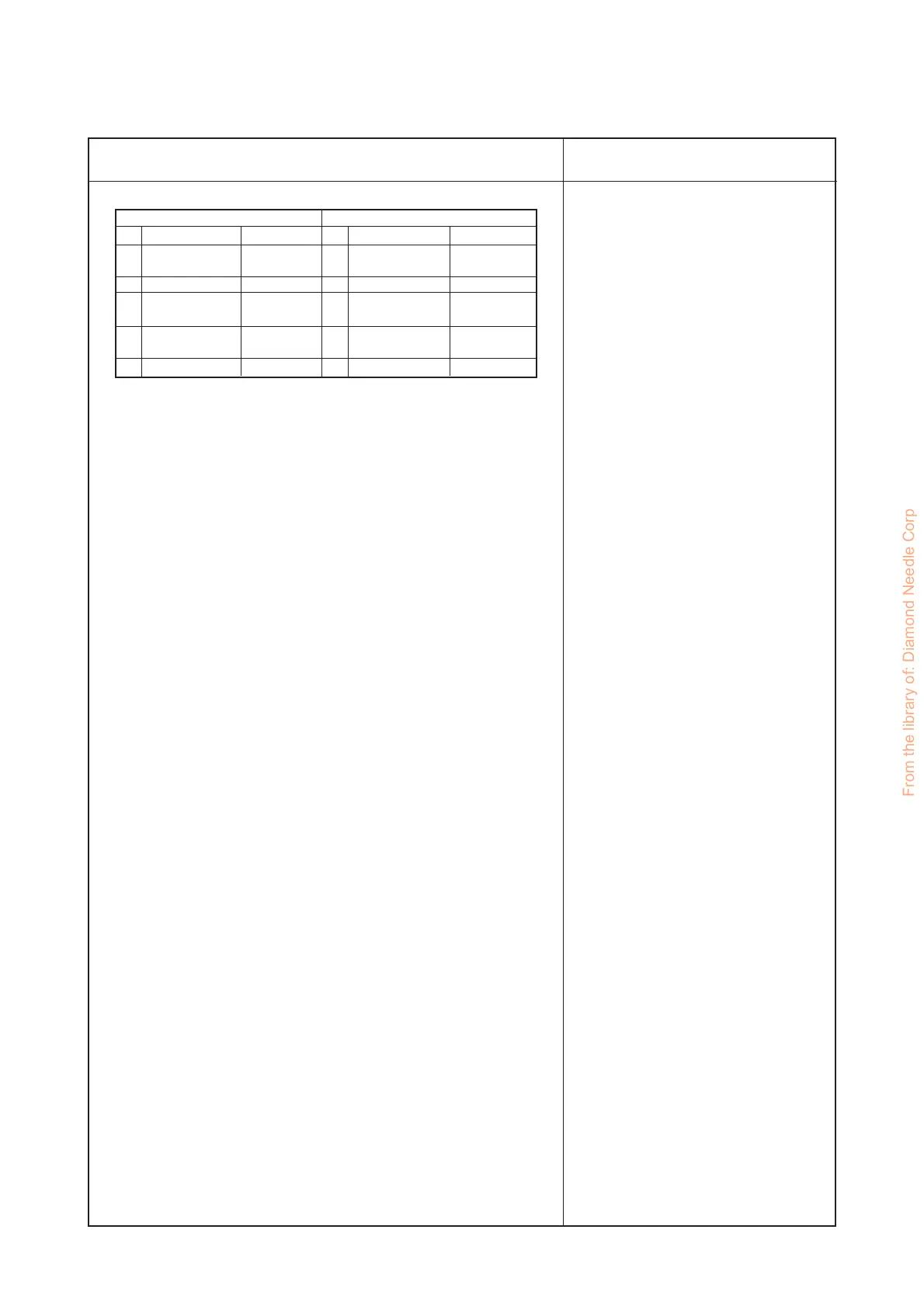
Part No.
US00050358Z
US00050317E
US0050363CL
US00050362R
SS6110480SP
Deleted parts Added parts
1
2
3
4
5
6
7
8
Name of part
Needle thread
strike-off asm.
Needle bar guard
Needle bar thread
guide
Part No.
US00050366B
US00050317C
US00050323P
Name of part
Needle bar cam
plate
Needle bar guard
Needle bar fork
thread take-up
Medium thread path
base
Screw
From the library of: Diamond Needle Corp
 Loading...