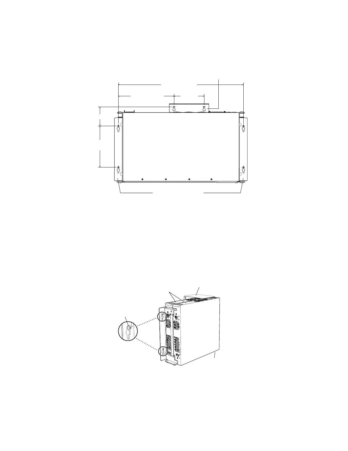
Figure 2: Measuring for Mounting Screws
18.68 in. (47.4 cm)
Front
Rear
A
E F
C
B
D
Side wall-mount brackets
8.32 in. (21.1 cm)
4.49 in.
(11.4 cm)
5.98 in.
(15.2 cm)
2.76 in (7 cm)
g021067
Baffle for PoE Models
(EX2200-24P and EX2200-48P)
4. Lift the unit (one switch or two) by grasping each side, and hang the unit by
attaching the brackets to the mounting screws as shown in Figure 3.
5. For PoE models, install the baffle by attaching it to mounting screws E and F as
shown in Figure 3.
6. Tighten all mounting screws.
Figure 3: Mounting a Switch on a Wall
g020723
Hang attached brackets
on wall-mounted screws.
Front
panel
Rear
panel
Baffle for PoE Models
(EX2200-24P and EX2200-48P)
Related Topics ■ Connecting AC Power to an EX2200 Switch
■ Connecting and Configuring an EX Series Switch (CLI Procedure)
Mounting an EX2200 Switch on a Wall ■ 3