EasyManuals Logo

Juniper QFX5120 Series Hardware Guide

Juniper QFX5120 Series
207 pages
To Next Page IconTo Next Page
To Previous Page IconTo Previous Page
Page #103 background imageLoading...
Page #103 background image
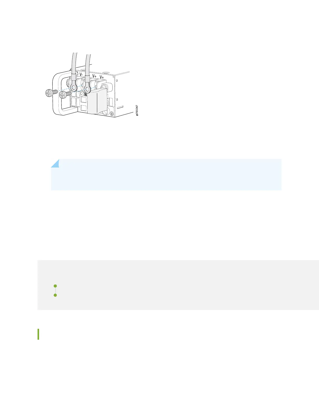
Figure 51: Securing Ring Lugs to the Terminals on the QFX51200-48Y DC Power Supply
8. Replace the terminal block cover.
9. Close the input circuit breaker.
NOTE: The switch powers on as soon as power is provided to the power supply. There is no
power switch on the device.
10. Verify that the IN and OUT LEDs on the power supply are lit green and are on steadily.
Connecting the QFX5120 to the Network
IN THIS SECTION
Installing a Transceiver | 106
Connecting a Fiber-Optic Cable | 109
Installing a Transceiver
The transceivers for Juniper Networks devices are hot-removable and hot-insertable field-replaceable
units (FRUs). You can remove and replace them without powering off the device or disrupting the device
functions.
106

Table of Contents

Other manuals for Juniper QFX5120 Series

Questions and Answers:

Question and Answer IconNeed help?

Do you have a question about the Juniper QFX5120 Series and is the answer not in the manual?

Juniper QFX5120 Series Specifications

General IconGeneral
Rack Units1 U
Junos OSYes
Form FactorFixed
Power SupplyDual, hot-swappable
CoolingFront-to-back or back-to-front airflow
FansHot-swappable
Operating Temperature32°F to 104°F (0°C to 40°C)
Storage Temperature-40°F to 158°F (-40°C to 70°C)
Humidity5% to 90% non-condensing
AC Power Input100 to 240 VAC
Management Ports1x RJ-45 console, 1x USB, 1x RJ-45 management

Related product manuals