How to Set Up Your SRX1500 Services Gateway
4
Power On the Device
1. If you are using the AC model, perform the following steps:
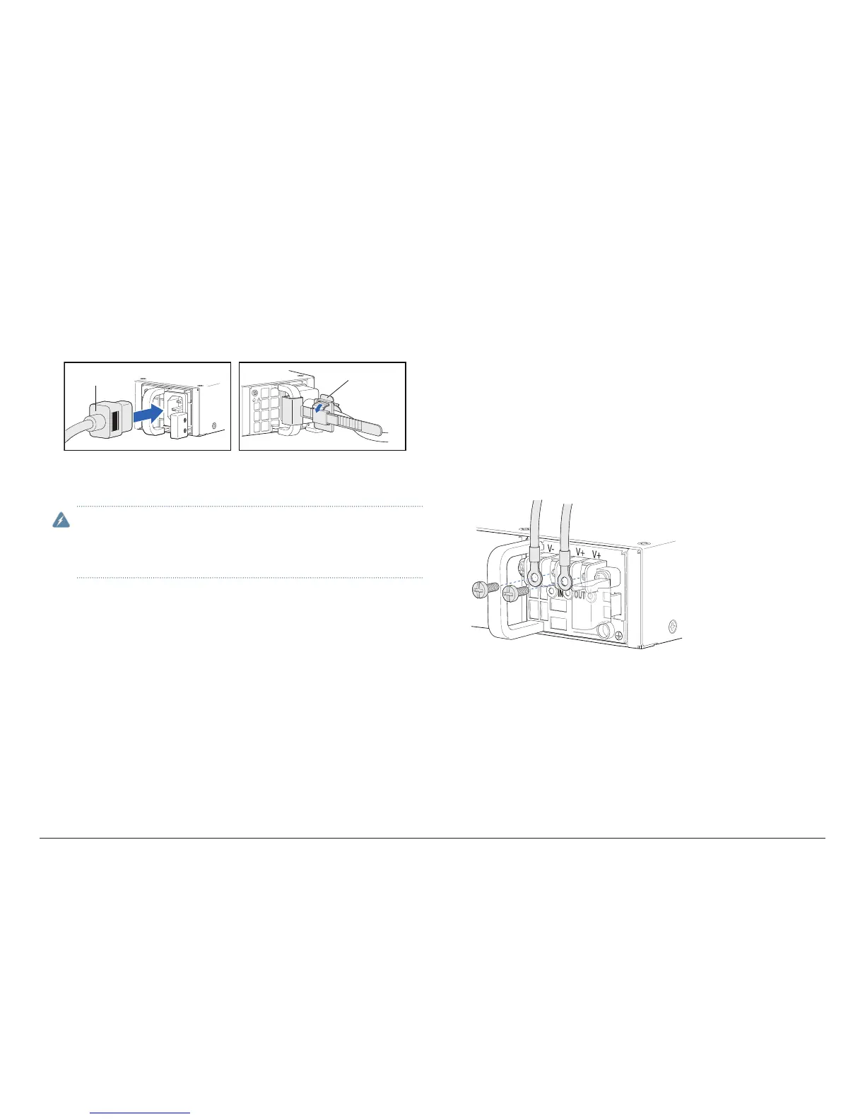
a. Insert the appliance coupler end of the power cord into the appliance inlet
on the power supply and the power cord plug into an external AC power
source receptacle. Use a power cord retainer to hold the power cord in
place.
Power cord Power cord
retainer
b. Turn on the power to the AC power receptacle
2. If you are using the DC model, perform the following steps:
WARNING: Before performing the following procedure, ensure that
there is no power in the DC circuit. To ensure that all power is cut o,
locate the circuit breaker on the panel board that services the DC circuit,
switch the circuit breaker to the OFF (0) position, and tape the switch
handle of the circuit breaker in the OFF position.
a. Ensure that the voltage across the DC power source cable leads is 0 V
and that the cable leads do not become active while you are connecting
DC power.
b. Verify that the DC power cables are correctly labeled before making
connections to the power supply. In a typical power distribution scheme
where the return is connected to chassis ground at the battery plant, you
can use a multimeter to verify the resistance of the -48V and RTN DC
cables to chassis ground:
• The cable with very high resistance (indicating an open circuit) to chassis
ground will be connected to the V- (input) DC power input terminal.
• The cable with very low resistance (indicating a closed circuit) to chassis
ground will be connected to the V+ (return) DC power input terminal.
c. Remove the clear plastic cover from the terminal studs on the faceplate.
d. Remove the screws on the terminals by using a Phillips (+) screwdriver,
number 2.
e. Secure each positive (+) DC source power cable lug to a RTN (return)
terminal. Secure each negative (–) DC source power cable lug to a -48V
(input) terminal.