(No.MA189)1-9
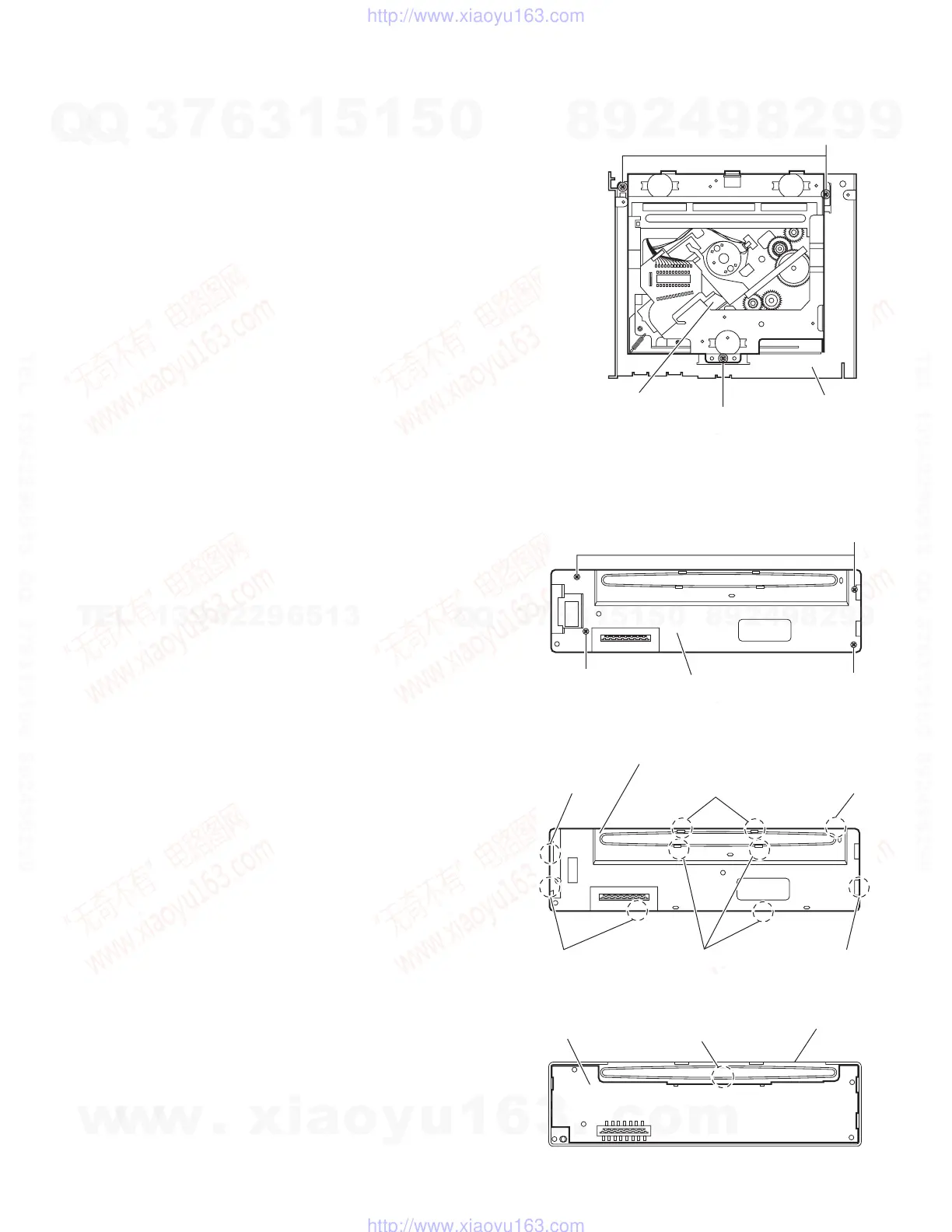
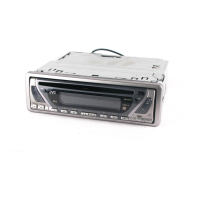
3.1.7 Removing the CD mechanism assembly
(See Fig. 7)
• Remove the front panel assembly, bottom cover, front chassis
assembly, heat sink, rear bracket and main board.
Remove the three screws H and take out the CD mechanism as-
sembly from the top chassis.
Fig.7
3.1.8 Removing the switch board
(See Figs.8 to 10)
• Remove the front panel assembly.
(1) From the back side of the front panel assembly, remove the
four screws J attaching the rear cover. (See Fig.8.)
(2) Release the ten joints f and remove the rear cover. (See
Fig.9.)
(3) Release the joint g and take out the switch board from the
front panel assembly. (See Fig.10.)
Fig.8
Fig.9
Fig.10
H
H
CD mechanism assembly
Top chassis
J
J
J
Rear cover
Joints f
Joint f Joints f
Joints f
Joints
Joint f
Rear cover
Switch board
Joint g
Front panel assembly
w
w
w
.
x
i
a
o
y
u
1
6
3
.
c
o
m
Q
Q
3
7
6
3
1
5
1
5
0
9
9
2
8
9
4
2
9
8
T
E
L
1
3
9
4
2
2
9
6
5
1
3
9
9
2
8
9
4
2
9
8
0
5
1
5
1
3
6
7
3
Q
Q
TEL 13942296513 QQ 376315150 892498299
TEL 13942296513 QQ 376315150 892498299
http://www.xiaoyu163.com
http://www.xiaoyu163.com