(No.49837)1-39
4.13 MN101C30ACK1 (IC251) : Unit micon
• Pin Layout
• Pin function
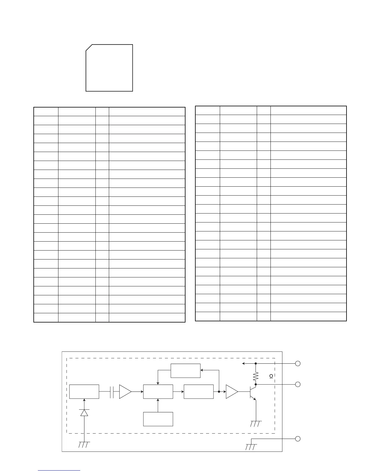
4.14 RPM6938-V4 (IC602) : Remocon reseiver
• Block diagram
64 49
4
3
17 32
1
16
Pin No. Symbol I/O Function
1,2 /SW1, /SW2 I SW1,SW2 input
3 /SW3 I Connect to ground
4 PCHKCD I Connect to ground
5 PCHKVCD I Connect to ground
6 VREF+ I Connect to VDD
7 VDD - Power supply
8 OSC2 O Xtal output
9 OSC1 I Xtal input
10 VSS - Ground
11 XI I Connect to ground
12 NC - Not connect
13 MMOD I Connect to ground
14 MSTAT O Status output
15 KCMD I Command input
16,17 NC - Not connect
18 SUBQ I/O SubQ. data
19 SQCK I/O SubQ. clock
20 /VCDRST I/O VCD reset
21 /CDMRST I Micon reset
22 NC - Not connect
23 UDSASTB I/O ES3883 STB for uDSA
24 UDSADAT I/O ES3883 DAT for uDSA
25 UDSAACK I/O ES3883 ACK for uDSA
26 NC - Not connect
27 BLKCK I SubQ. blk. clk
28 GND - Ground
29 PS2 I PS2
30,31 GND - Ground
32 DSASTB I/O ES3880 STB for DSA
33 DSADAT I/O ES3880 DAT for DSA
34 DSAACK I/O ES3880 ACK for DSA
35 PS1 I/O PS1 slave
36 to 48 NC - Not connect
49 REST I/O Rest SW
50 LM O Loading motor control
51 MSW I/O Motor control SW
52 to 55 NC - Not connect
56 /LSIRST O CD LSI reset output
57 STAT I/O Status
58 MDATA I/O Com.data
59 MCLK I/O Com.clock
60 MLD I/O Com.load
61 VREF- I Connect to ground
62 /TLOCK I Tracking lock signal input
63 /FLOCK I Focus lock signal input
64 SENSE I Sense signal input
Pin No. Symbol I/O Function
I/V
conversion
AMP
PD
magnetic shield
BPF Detector
for
trimming
circuit
AGC
Vcc
Comp
22k
Vcc
ROU
GND

 Loading...