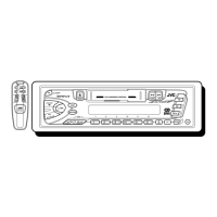
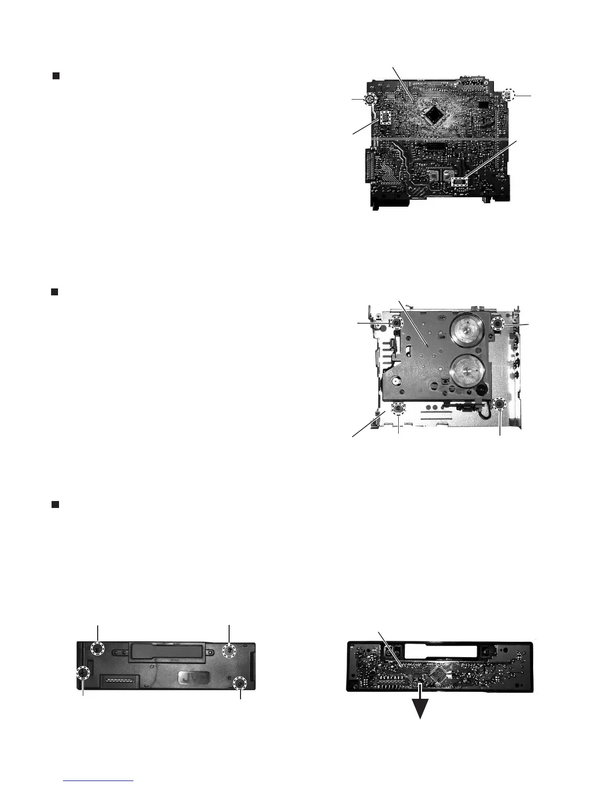
Removing the main amplifier board assembly
(See Fig.4 and 5)
Removing the Cassette mehanism assembly
(See Fig.6)
1.
2.
3.
4.
5.
Remove the front chassis.
Remove the bottom cover.
Remove the rear pan.
Remove the two screws B attaching the main amplifier
board assembly on the top cover.
Disconnect connector CN901 and CN902 on the main
amplifier board assembly from the cassette mechanism
assembly.
1.
2.
3.
4.
Remove the front chassis.
Remove the bottom cover.
Remove the main amplifier board assembly.
Remove the tore screws F attaching the cassete
mechanism assembly from the top cover.
Removing the control switch board
(See Fig.7 and 8 )
1.
2.
3.
Remove the front panel unit from the main body.
Remove the four screws G attaching the rear cover on
the back of the front panel unit.
Remove the control switch board from the front panel
unit.
Fig.4
E
E
Cassete mechanism assembly
F
F
F
Top cover
Fig. 6
G
G
G
G
Fig. 7
Fig. 8
Control switch board
CN901
Main amplifier board
F
CN902
 Loading...