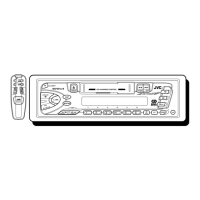
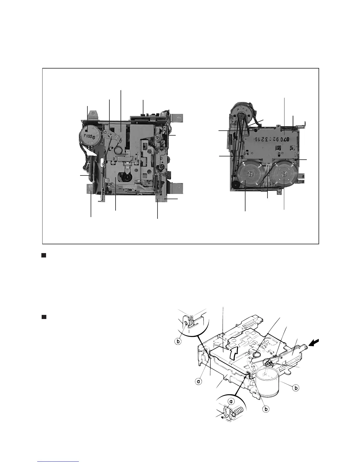
(Cassette Mechanism Sections)
Head amplifier board
Direction
switch board
Motor assembly
Cassette hanger
Relay board
Center plate
Cassette holder
FF Lever
REW Lever
Chassis
Main belt
Sub-belt
Reel base assembly
Flywheel
assembly(B)
Flywheel
assembly(F)
8
7
7
7
Fig. 1
Fig. 2
Fig. 3
To see
Fig.5
Removing the Main Parts of Cassette Mechanism
1. Remove the cassette hanger and FF, REW, EJECT lever etc. , when you need to replace or adjusting head.
2. The main belt can be replaced directly.
3. To change the sub-belt, remove the three screws 7and loosen one screw 8.
Then raise the belt side of the reel base assembly slightly.
Removing the Cassette Hanger
(See Fig.1-5 )
1. From the rear of the unit, bend the
cassette hanger and chassis the five claws
a, boutwards.
2. While pressing the EJECT lever, remove the
cassette hanger.
3. Remove the return ink rod from the center plate
of the cassette hanger.
Cassette hanger
Center plate
Return link
EJECT lever
Chassis
Claw
Claw
 Loading...