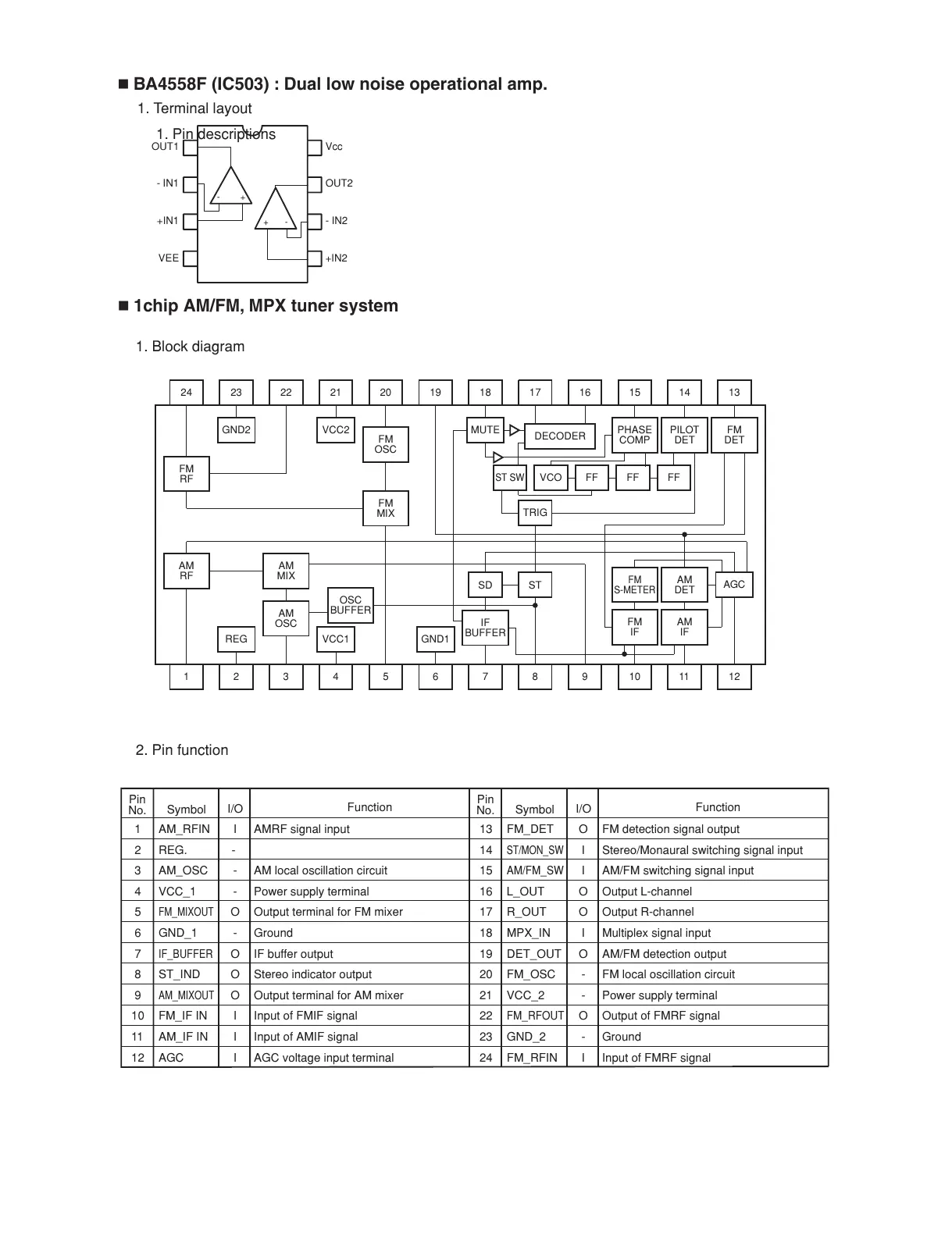
1. Terminal layout
-+
+-
OUT1
- IN1
+IN1
VEE
Vcc
OUT2
- IN2
+IN2
BA4558F (IC503) : Dual low noise operational amp.
1chip AM/FM, MPX tuner system
Pin
No.
Symbol
Function
I/O
Pin
No.
Symbol
Function
I/O
2. Pin function
1. Block diagram
1 AM_RFIN I AMRF signal input
2 REG. -
3 AM_OSC - AM local oscillation circuit
4 VCC_1 - Power supply terminal
5
FM_MIXOUT
O Output terminal for FM mixer
6 GND_1 - Ground
7
IF_BUFFER
O IF buffer output
8 ST_IND O Stereo indicator output
9
AM_MIXOUT
O Output terminal for AM mixer
10 FM_IF IN I Input of FMIF signal
11 AM_IF IN I Input of AMIF signal
12 AGC I AGC voltage input terminal
13 FM_DET O FM detection signal output
14
ST/MON_SW
I Stereo/Monaural switching signal input
15
AM/FM_SW
I AM/FM switching signal input
16 L_OUT O Output L-channel
17 R_OUT O Output R-channel
18 MPX_IN I Multiplex signal input
19 DET_OUT O AM/FM detection output
20 FM_OSC - FM local oscillation circuit
21 VCC_2 - Power supply terminal
22
FM_RFOUT
O Output of FMRF signal
23 GND_2 - Ground
24 FM_RFIN I Input of FMRF signal
24
FM
RF
FM
OSC
23
GND2
21
VCC2
20
FM
MIX
PHASE
COMP
15
PILOT
DET
14
FM
DET
1319 18
MUTE
17 16
DECODER
22
1 2 4 5 10 11 126 7 8 93
ST SW
FM
S-METER
AM
DET
VCO FF FF
TRIG
STSD
FF
AGC
FM
IF
AM
IF
AM
RF
REG VCC1 GND1
AM
MIX
AM
OSC
OSC
BUFFER
IF
BUFFER
1. Pin descriptions

 Loading...