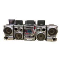
Fig.20
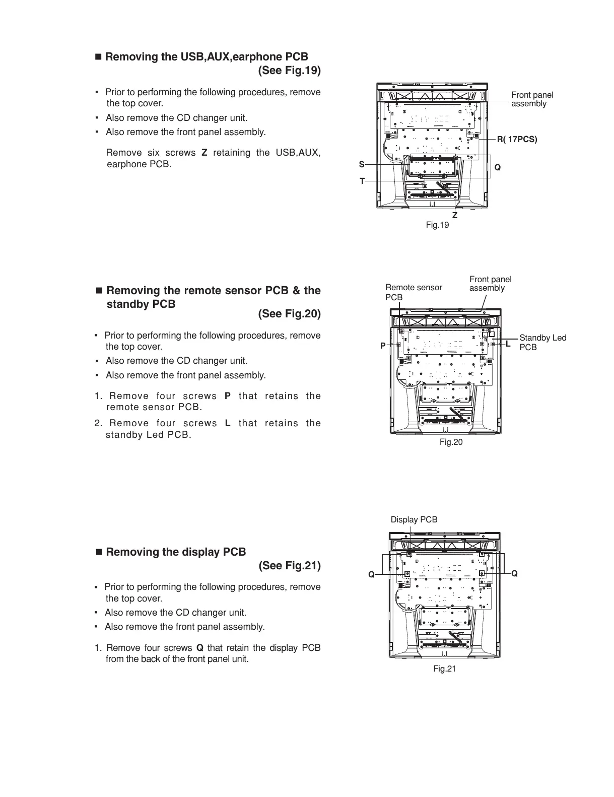
Fig.19
S
Q
R( 17PCS)
T
Z
P
L
Front panel
assembly
Remote sensor
PCB
Standby Led
PCB
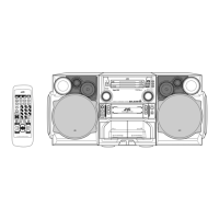
Fig.21
Removing the USB,AUX,earphone PCB
(See Fig.19)
Prior to performing the following procedures, remove
the top cover.
Also remove the CD changer unit.
Also remove the front panel assembly.
Remove six screws
Z
retaining the USB,AUX,
earphone PCB.
Removing the remote sensor PCB & the
standby PCB
(See Fig.20)
Prior to performing the following procedures, remove
the top cover.
Also remove the CD changer unit.
Also remove the front panel assembly.
1. Remove four screws
P
that retains the
remote sensor PCB.
2. Remove four screws
L
that retains the
standby Led PCB.
Removing the display PCB
(See Fig.21)
Prior to performing the following procedures, remove
the top cover.
Also remove the CD changer unit.
Also remove the front panel assembly.
1. Remove four screws
Q
that retain the display PCB
from the back of the front panel unit.
Q
Q
Front panel
assembly
Display PCB