RC-BM5
1-11
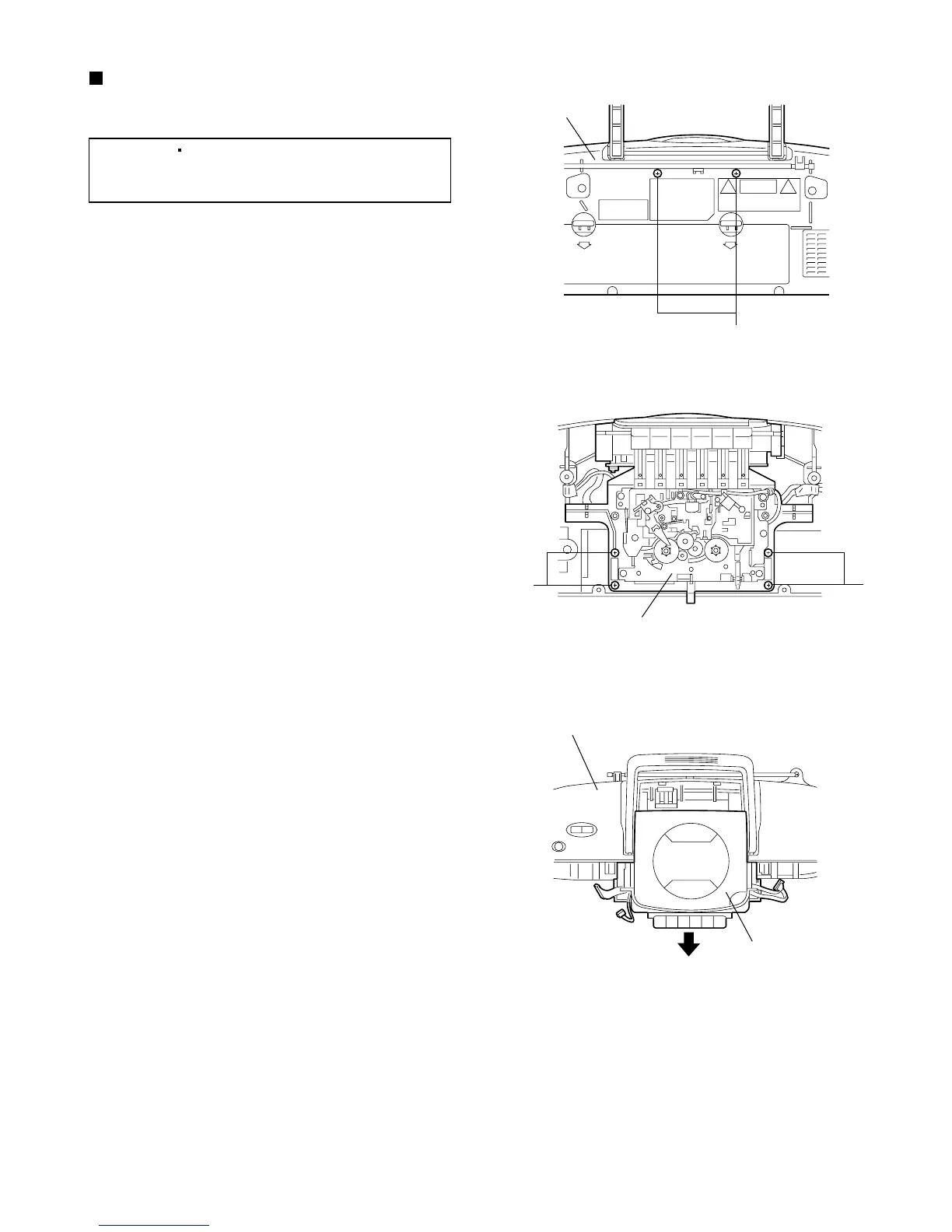
Fig.20
S
Rear cabinet
assembly
Fig.22
CD/Cassette mechanism
assembly
Rear cabinet assembly
Fig.21
TT
CD/Cassette mechanism assembly
Removing the CD/Cassette mechanism
assembly
(See Figs. 12,14,16 and 20 to 22.)
1.
2.
3.
4.
5.
6.
7.
From the back side of the rear cabinet assembly,
remove the two screws S retaining the
CD/Cassette mechanism assembly. (See Fig.12.)
Disconnect the wire from the connector H402 on
the volume switch board. (See Fig.12.)
Disconnect the wire from the connector CN206 on
the power amplifier board. (See Fig.14.)
Disconnect the wire from the connector CN801 on
the main board. (See Fig.14.)
Disconnect the wire from the connector H801 on
the tuner board. (See Fig.16.)
Remove the four screws T retaining the
CD/Cassette mechanism assembly. (See Fig.21.)
Slide the CD/Cassette mechanism assembly in the
direction of the arrow and take out it. (See Fig.22.)
[Reference]
It is not necessary to remove the
cassette deck mechanism assembly
from the rear cabinet assembly.
 Loading...