RC-BM5
1-9
Fig.14
Fig.15
Fig.12
GG
G
Volume switch board
Control bracket
H402
H
Volume switch
board
Fig.13
L
K
K
Board holder (A)
Notch s
Notch t
Phone jack
board
Soldered section r
CN206
Main board
Power amplifier board
CN801
H
M
N
Soldered section u
Soldered section v
Wire(blue)
Power transformer
Wire(black)
AC jack
Tie band
Control bracket
Board holder (B)
J
Volume switch
H
(Bottom side)
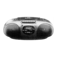
Removing the volume switch board
(See Fig. 12 and 13.)
1.
2.
3.
4.
5.
Disconnect the wire from the connector H402 on
the volume switch board.
Remove the four screws G retaining the control
bracket of the volume switch board.
While pressing the power and volume buttons of
the volume switch board, take out the volume
switch board.
From the forward side of the volume switch board,
remove the five screws H retaining the volume
switch board to the control bracket. (See Fig.13.)
From the bottom side of the control bracket,
remove the two screws J retaining the volume
switch board and volume button to the control
bracket. (See Fig.13.)
<Rear cabinet section>
Prior to performing the following procedures,
remove the front cabinet assembly from the rear
cabinet assembly.
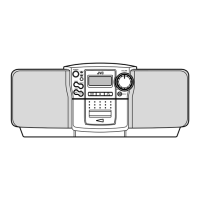
Removing the power amplifier board
and phone jack board (See Fig. 14.)
1.
2.
3.
4.
5.
6.
Disconnect the wire from the connector CN206 on
the power amplifier board.
Disconnect the wire from the connector CN801 on
the main board.
Remove the wire from the soldered section r on the
power amplifier board.
Remove the two screws K and board holders
(A)/(B) retaining the power amplifier board.
Remove the two screws L retaining the phone jack
board.
Pull out the power amplifier board from notches s
and t, and then take out the power amplifier board
together the phone jack board.
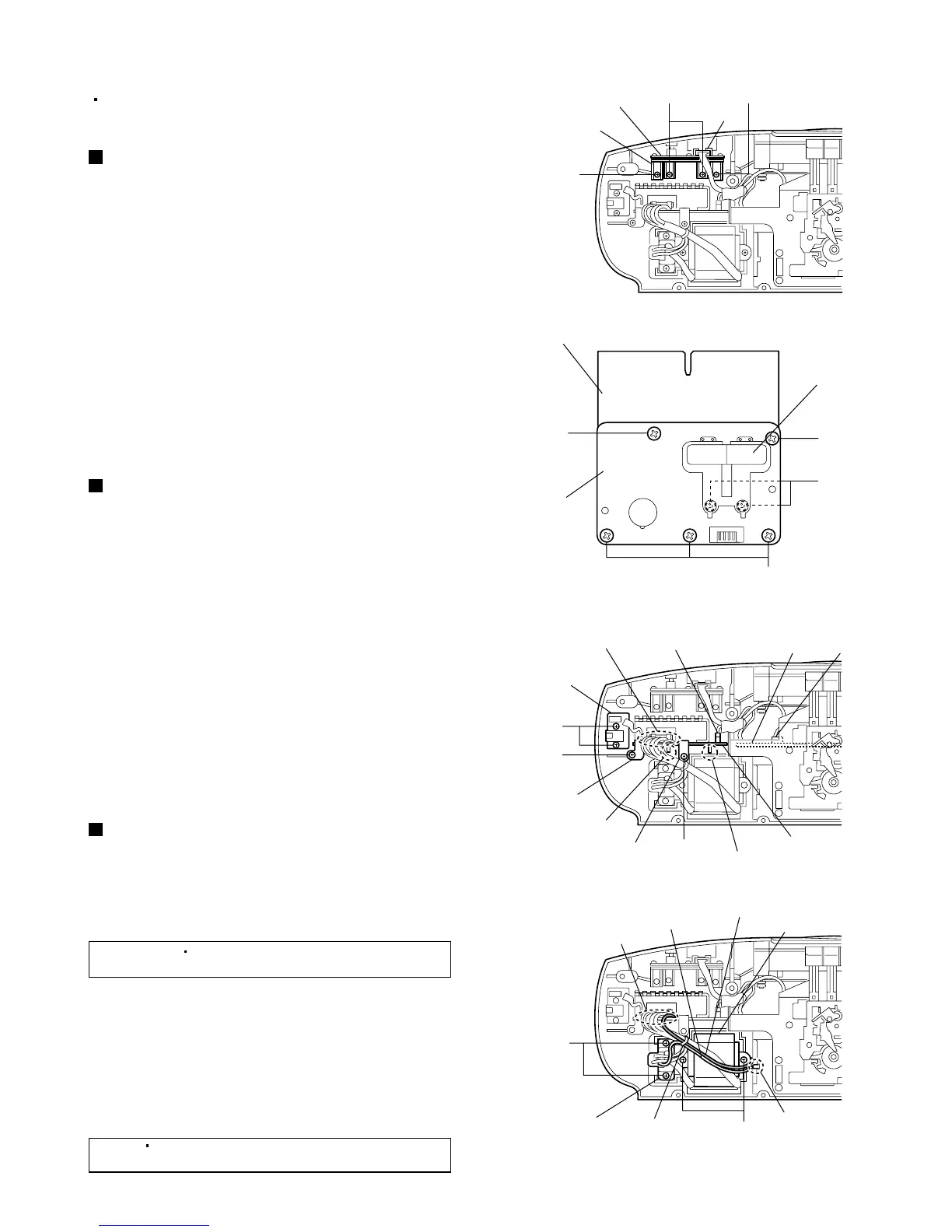
Removing the power transformer
(See Fig. 15.)
1.
2.
Remove the tie band bundling the wires from the
power transformer and battery plate.
Remove the wire from the soldered section u on
the power amplifier board.
[Reference]
It is not necessary to remove the
wire(black) from the battery plate.
3.
4.
5.
6.
Remove the wire(blue) from the soldered section v
of the battery plate.
Remove the two screws M retaining the power
transformer.
Remove the two screws N retaining the AC jack.
Take out the power transformer together the AC
jack.
[Note]
After assembly, apply a locking agent to
the screws M.

 Loading...