RC-BM5
1-6
1
2
1
1
2
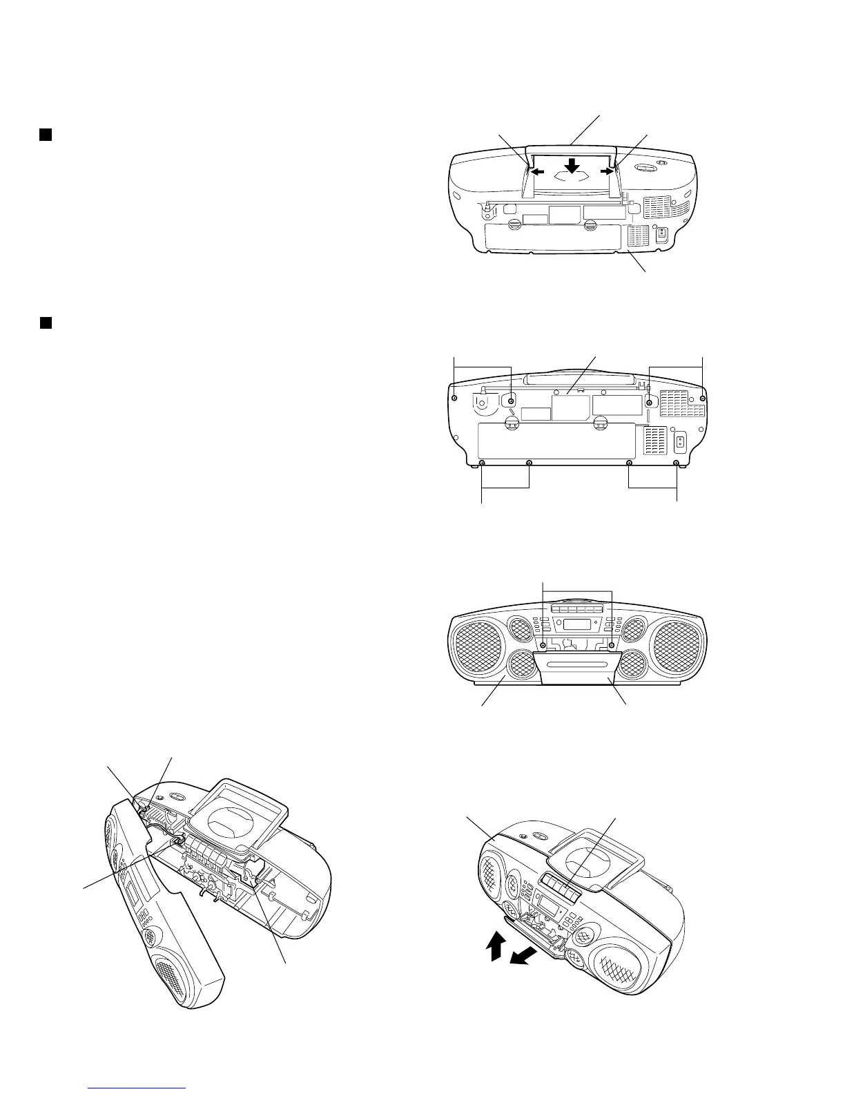
Fig.4
Fig.1
Claw aClaw a
Handle
Rear cabinet assembly
Fig.2
AA
AA
Rear cabinet assembly
B
Front cabinet assembly Cassette door
Fig.3
Front cabinet assembly
Cassette knobs
Fig.5
Phone jack board
CN205
CN302
Main board
Removing the front cabinet assembly
and rear cabinet assembly
(See Figs. 2 to 5.)
<Main body section>
Disassembly method
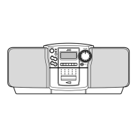
Removing the handle (See Fig. 1.)
1.
2.
3.
4.
5.
6.
7.
Remove the eight screws A retaining the front
cabinet and rear cabinet assemblies from the rear
of the main body. (See Fig.2.)
Open the cassette door. (See Fig.3.)
Remove the two screws B retaining the front
cabinet assembly. (See Fig.3.)
Slide the lower part of the front cabinet slightly in
the direction of the arrow 1. (See Fig.4.)
While removing the front cabinet assembly from the
cassette knobs and remove it in the upward
direction 2. (See Fig.4.)
Disconnect the speaker wire from the connector
CN205 on the phone jack board. (See Fig.5.)
Disconnect the parallel wire from the connector
CN302 on the main board. (See Fig.5.)
Lift the handle slightly.
While pressing the claws a of the rear cabinet
assembly in the direction of the arrow 1, slide the
handle in the direction of the arrow 2.
1.
2.
 Loading...