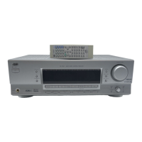
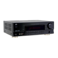
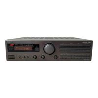
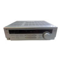
RX-5030VBK
1-10 (No.22025)
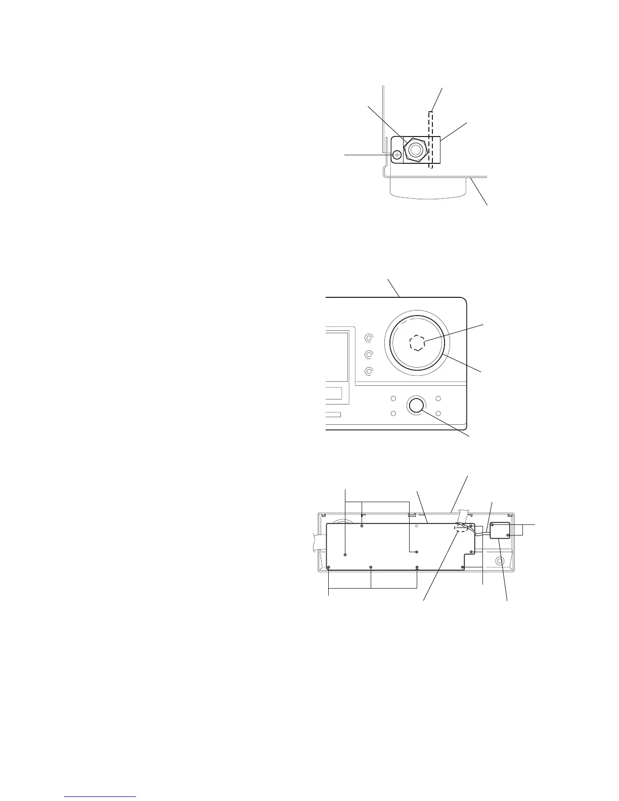
2.14 Removing the headphone jack board
(See Figs.14 and 15)
• Prior to performing the following procedure, remove the top
cover and front panel assembly.
(1) From the top side of the main body, disconnect the parallel
wire from the connector CN101 on the headphone jack
board. (See Fig.14)
(2) From the front side of the main body, remove the nut and
screw S attaching the Bracket(phones) to the chassis
base. (See Fig.15)
Fig.15
2.15 Removing the system control board and power switch board
(See Figs.16 and 17)
• Prior to performing the following procedure, remove the top
cover and front panel assembly.
(1) Pull out the volume and jog knobs from the front side of the
front panel assembly, remove the nut attaching the system
control board. (See Fig.16)
(2) From the back side of the front panel assembly, remove the
nine screws T attaching the system control board. (See
Fig.17)
(3) Remove the solders of the soldered section i on the system
control board and disconnect the parallel wire. (See Fig.17)
(4) Remove the two screws U attaching the power switch
board. (See Fig.17)
Fig.16
Fig.17
Headphone jack board
Nut
Chassis base
Bracket(phones)
S
Nut
Volume knob
Front panel assembly
Jog knob
T
T
T
U
Soldered section i
Power switch board
System control board
Parallel wire
Front panel assembly
 Loading...