RX-5030VBK
(No.22025)1-9
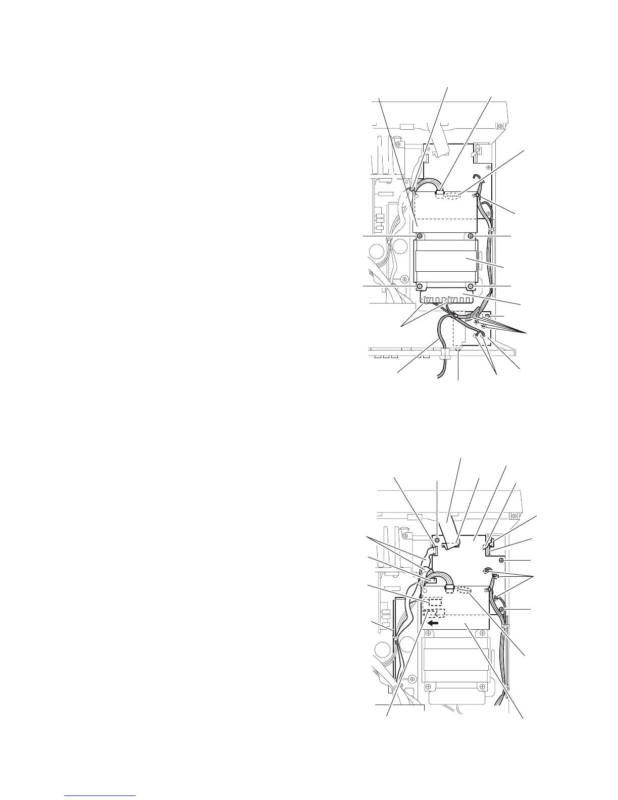
2.11 Removing the power transformer
(See Fig.13)
• Prior to performing the following procedure, remove the top
cover.
(1) From the top side of the main body, remove the tie bands
fixing the wires.
(2) Remove the solders from the soldered section c on the
power transformer board 1.
(3) Remove the solders from the soldered sections d on the
power transformer board 2.
(4) Disconnect the wire from the connector CN251 on the pow-
er transformer board 1.
(5) Remove the four screws N attaching the power transform-
er.
2.12 Removing the power/fuse board
(See Fig.13)
• Prior to performing the following procedure, remove the top
cover.
(1) From the back and top sides of the main body, remove the
screw P and screw Q attaching the power/fuse board.
(2) Remove the solders from the soldered sections e attaching
the power cord.
(3) From the reverse side of the power/fuse board, remove the
solders from the soldered sections f attaching the wires.
Fig.13
2.13 Removing the power supply board
(See Fig.14)
• Prior to performing the following procedure, remove the top
cover.
(1) From the top side of the main body, disconnect the parallel
wires from the connectors CN203 and CN241 on the power
supply board.
(2) Disconnect the card wire from the connector CN201 on the
power supply board.
(3) Disconnect the relay board from the connector CN291 on
the power supply board.
(4) Disconnect the parallel wire from the connector CN101 on
the headphone jack board.
(5) Remove the solders from the soldered section c on the
power transformer board 1.
(6) Remove the three screws R attaching the power supply
board.
(7) Remove the power supply board from the hook g of the
chassis base bracket in the direction of the arrow, take out
the power supply board.
(8) Turn over the power supply board, remove the solders from
the soldered sections h attaching the wires.
Fig.14
CN251
Soldered
section c
Soldered
sections d
Soldered
sections e
Soldered
sections f
Tie band
Tie band
Power
transformer
Power
transformer
board 2
Power cord
N
N
Q
P
N
N
Power transformer
board 1
Power / Fuse
board
R
R
R
Card wire
CN201
CN101
Headphone
jack
board
CN241
CN203
Relay
board
CN291
Power transformer
board 1
Soldered
section c
Soldered
section h
Hook g of the
chassis base bracket
Parallel
wires
Parallel wire
Power supply
board
 Loading...