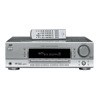
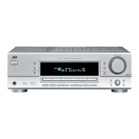
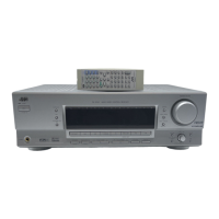
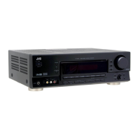
RX-5030VBK
1-8 (No.22025)
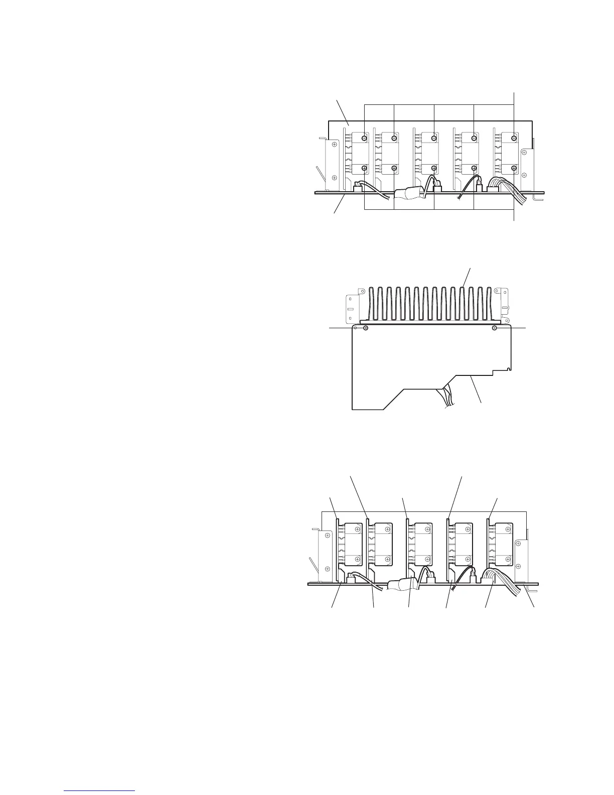
2.9 Removing the heat sink
(See Figs.10 and 11)
• Prior to performing the following procedure, remove the top
cover and main board.
(1) Remove the ten screws L attaching the heat sink. (See
Fig.10)
(2) From the reverse side of the main board, remove the two
screws M attaching the heat sink. (See Fig.11)
Fig.10
Fig.11
2.10 Removing the center amp. board, front amp. boards (L/R) and rear amp. boards (L/R)
(See Figs.10 and 12)
• Prior to performing the following procedure, remove the top
cover and main board.
(1) Remove the ten screws L attaching the heat sink. (See
Fig.10)
(2) Disconnect the center amp. board from the connector
CN321 on the main board. (See Fig.12)
(3) Disconnect the front amp. board (L) from the connector
CN311 on the main board. (See Fig.12)
(4) Disconnect the front amp. board (R) from the connector
CN312 on the main board. (See Fig.12)
(5) Disconnect the rear amp. board (L) from the connector
CN331 on the main board. (See Fig.12)
(6) Disconnect the rear amp. board (R) from the connector
CN332 on the main board. (See Fig.12)
Fig.12
L
L
Heat sink
Main board
Heat sink
Main board
M
M
Rear amp.
board (R)
Front amp. board (R)
Center amp.
board
Rear amp. board (L)
Front amp. board (L)
CN332
CN331 CN312 CN311
CN321
Main board
 Loading...