RX-9010VBK
1-9
Prior to performing the following procedure, remove
the top cover and the front panel assembly.
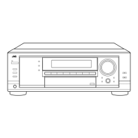
Pull out the volume knob on the front side of the front
panel and remove the nut attaching the system
control board.
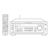
Remove the two screws P attaching the power
switch board.
Remove the two screws Q attaching the switch
board.
Remove the cords from the three hooks a.
Remove the eight screws R attaching the system
control board on the back of the front panel.
On the back of the front panel, release the four joints
by pushing the joint tabs inward.
Remove the operation switch panel toward the front.
Disconnect the harness from connector CN420 and
CN422 on the system control board.
Release the two hooks b attaching the system
control board.
1.
2.
3.
4.
5.
6.
7.
8.
Removing the system control board /
power switch board (See Fig.21 to 23)
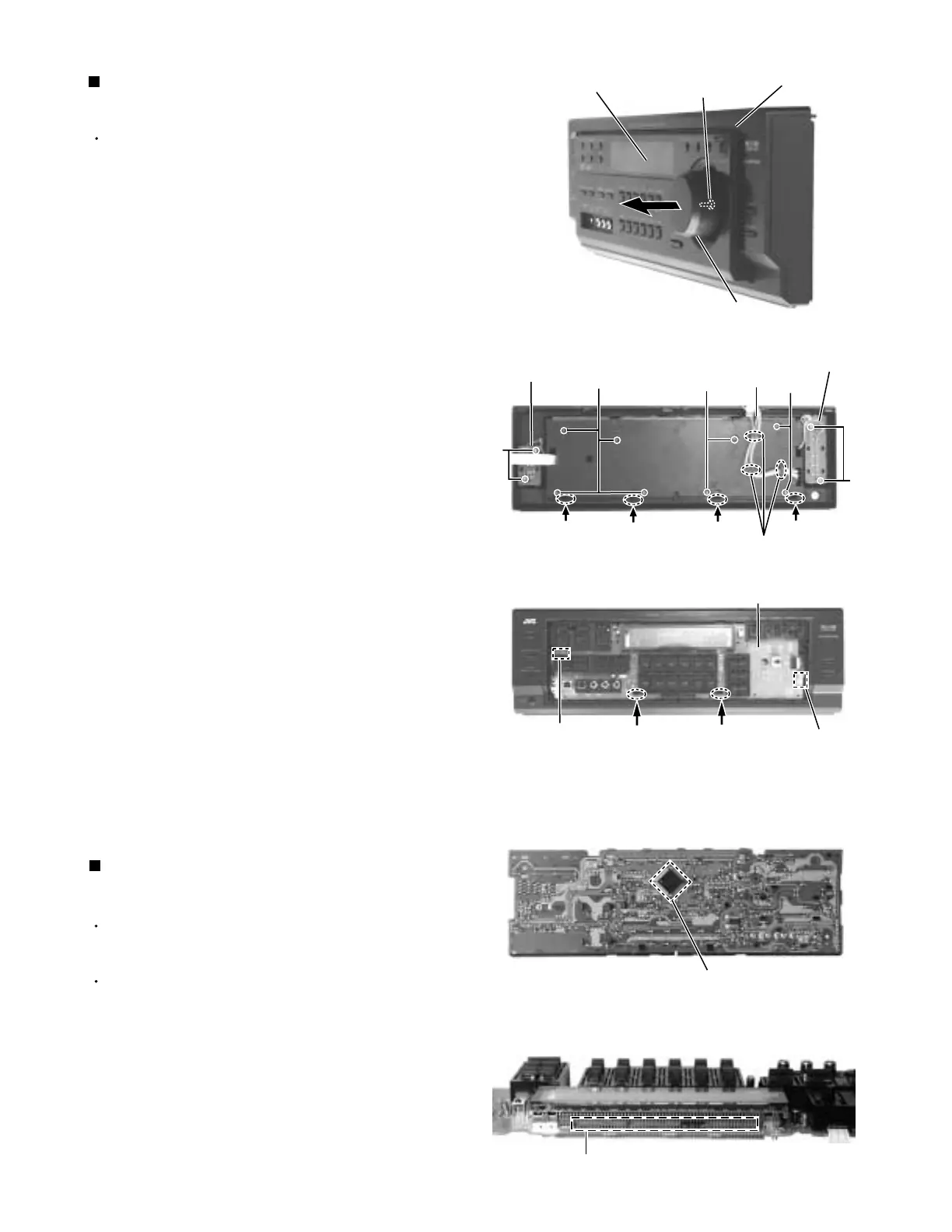
Matters that require attention during
replacement of IC400 (See Fig.24 to 25)
In case where there is a resistance array:
Both onetime IC and mask IC can be used
In case where there is no resistance array:
Only mask IC can be used
System control board reverse side
System control board top view
Fig.21
Fig.22
Fig.23
Front panel assembly
Nut
Volume knob
System control board
Power switch
board
R
R
CN422
P
Joint
Joint
Joint
Joint
Hook b
Hook b
Operation switch panel
Q
CN420
Switch
board
R
Hook a
Cords
Resistance array
IC400
Fig.24
Fig.25
 Loading...