(No.MB479)1-17
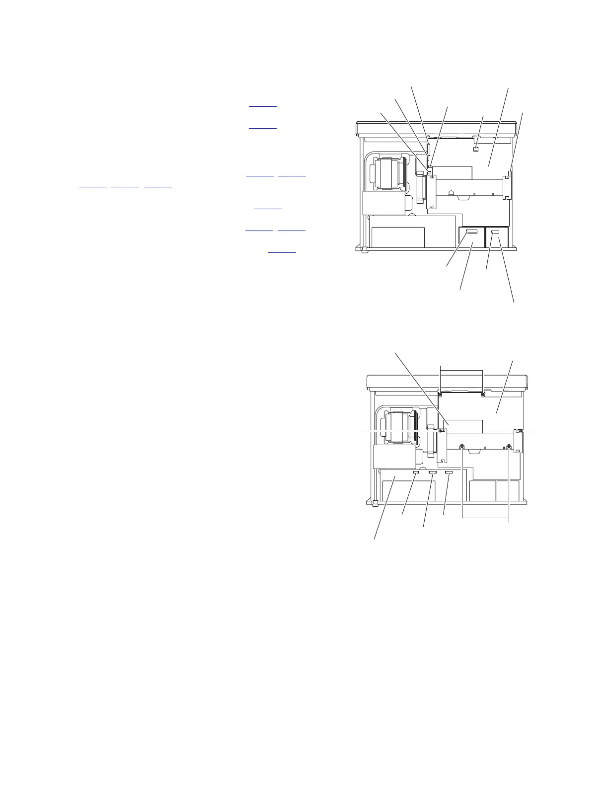
3.1.24 Removing the main amplifier board
(See Figs.19 and 20)
• Remove the top cover, tuner, front video board, DCDC control
board, PWM modulation 1 board, PWM modulation 2 board,
volume board, OSD connect 1 board and master clock board.
(1) Disconnect the wire from the connector CN265
on the
speaker terminal 1 board. (See Fig.19.)
(2) Disconnect the wire from the connector CN262
on the
speaker terminal 2 board. (See Fig.19.)
Reference:
Remove the tie bands bundling the wires.
(3) Disconnect the wires from the connectors (CN101
, CN103,
CN106
, CN111, CN351) on the main amplifier board. (See
Fig.19.)
(4) Disconnect the card wire from the connector CN102
on the
main amplifier board. (See Fig.19.)
(5) Disconnect the wires from the connectors (CN530
, CN531)
on the input board. (See Fig.20.)
(6) Disconnect the parallel wire from the connector CN540
on
the input board. (See Fig.20.)
(7) Remove the four screws Z and two screws AA. (See
Fig.20.)
(8) Take out the main amplifier board with the regulator board
from the main body. (See Fig.20.)
Fig.19
Fig.20
CN102
CN106
Main amplifier board
CN101
CN103
CN111
CN351
CN265
Speaker terminal 1 board
CN262
Speaker terminal 2 board
Main amplifier board
CN540
AA
Z
Z
Z
CN530
CN531
Input board
Regulator board

 Loading...


