(No.22008)1-11
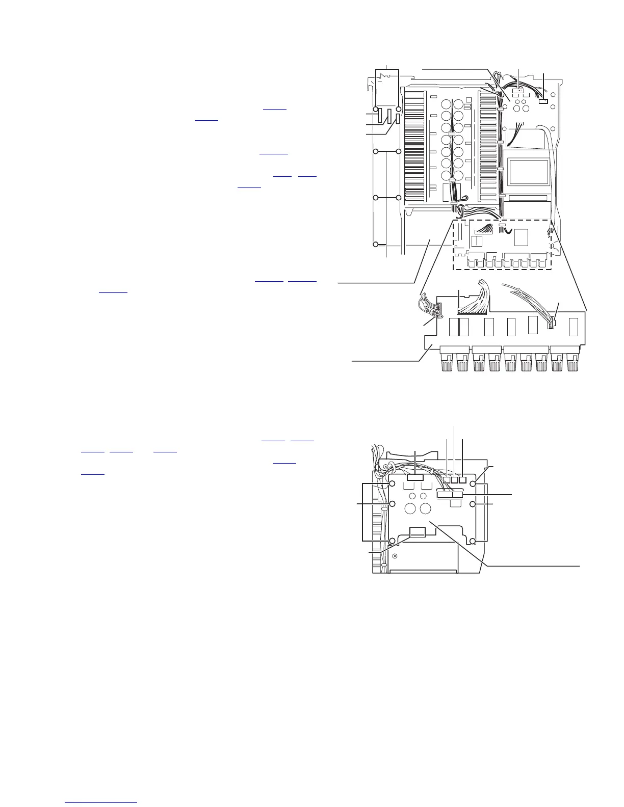
3.1.12 Removing the input base board
(See Fig.12)
• Prior to performing the following procedure, remove the top
cover, rear panel, DSP board, audio signal 1 board, audio sig-
nal 2 board, video board, S video board and V compo 1 board.
(1) Disconnect the harness from the connector CN62
on the
power supply 1 board and CN44
on the power supply 2
board.
And cut off the tie bands fixing the harness.
(2) Disconnect the harness from the connector CN743
on the
speaker board.
(3) Disconnect the card wire from the connector CN1
, CN2
and the harness from the connector CN11 on the input
base board.
(4) Remove the seven screws H attaching the input base
board.
3.1.13 Removing the speaker board
(See Fig.12)
• Prior to performing the following procedure, remove the top
cover and rear panel.
(1) Disconnect the harness from the connector CN741
, CN742
and CN743 on the speaker board.
Fig.12
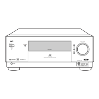
3.1.14 Removing the power supply 1 board
(See Fig.13)
• Prior to performing the following procedure, remove the top
cover.
(1) Disconnect the harness from the connector CN61
, CN62,
CN63, CN64 and CN65 on the power supply 1 board.
(2) Disconnect the harness from the connector CN44 and
CN45
on the power supply 2 board.
(3)
Fig.13
CN743
CN742
CN741
Speaker board
Input base board
Power supply
1 board
CN44
(on the power
supply 2 board)
CN62
H
CN2
CN1
CN11
H
CN63
CN64
CN62
CN44/CN45
(on the power
supply 2 board)
CN65
CN61
(fixing the
lug wire)
Power supply 1 board
II