(No.22008)1-13
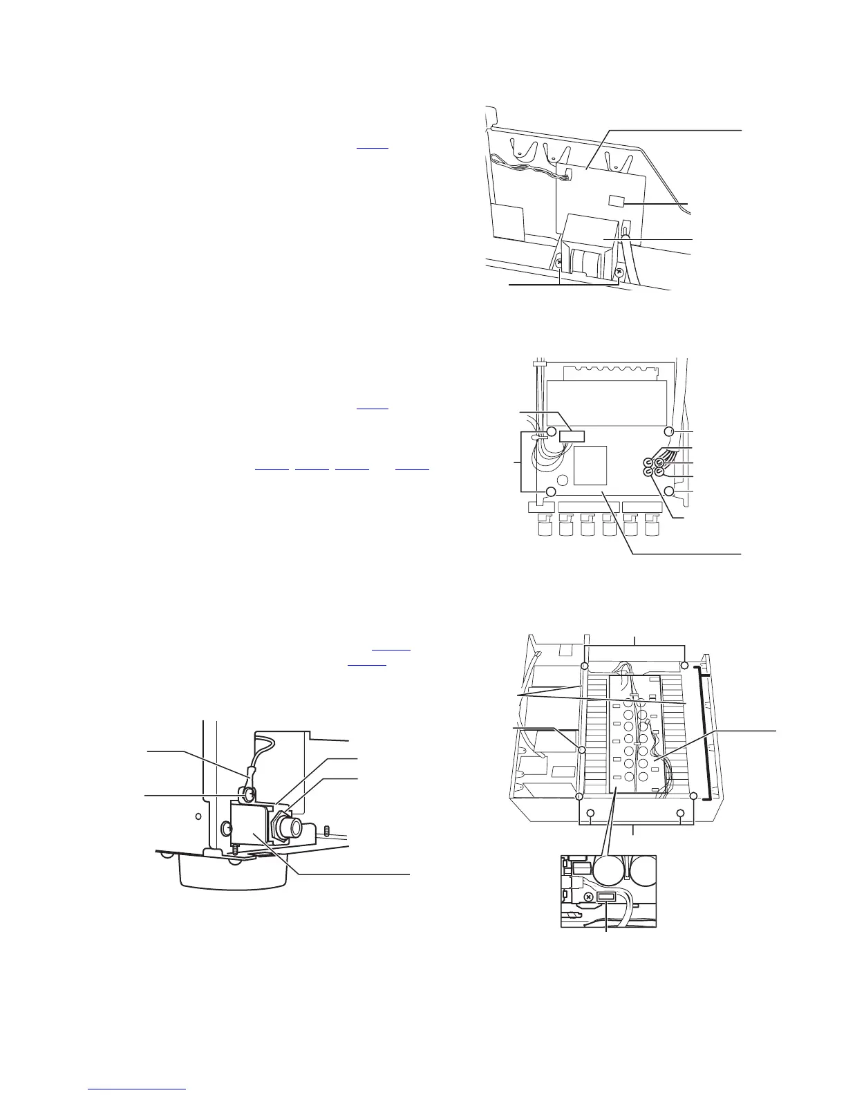
3.1.18 Removing the power transformer 3 with the power supply 3 board
(See Fig.17)
• Prior to performing the following procedure, remove the top
cover, power supply 1 board, power transformer 1 and power
transformer 2.
(1) Disconnect the harness from the connector CN41
on the
power supply 3 board.
(2) Remove the two screws M attaching the power transformer
3.
Fig.17
3.1.19 Removing the power/ fuse board
(See Fig.18)
• Prior to performing the following procedure, remove the top
cover, rear panel, power supply 1 board and power transform-
er 2.
(1) Disconnect the harness from the connector CN25
on the
power/ fuse board.
(2) Remove the four screws N attaching the power/ fuse
board.
(3) Unsolder the solder points PW21
, PW22, PW23 and PW24
on the power/ fuse board.
Fig.18
3.1.20 Removing the head phone board
(See Fig.19 and 20)
• Prior to performing the following procedures, remove the top
cover and front panel assembly.
(1) Disconnect the harnesses from the connector CN981
on
the system control board (see fig.5) and CN738 on the
power amp. board.
(2) Removing the nut O fixing the head phone board.
(3) Removing the screw P attaching the lug wire and bracket.
Fig.19
Fig.20
Power supply 3 board
CN41
M
Power
transformer 3
PW21 (blue)
PW22 (brown)
PW23 (red)
PW24 (white)
N
N
N
Power/ fuse board
CN25
P
O
Head phone board
Lug wire
Bracket
(Front side)
Q
Q
R
Power
amp.
assembly
Power amp.
board
Barrier
CN738