1-14 (No.22008)
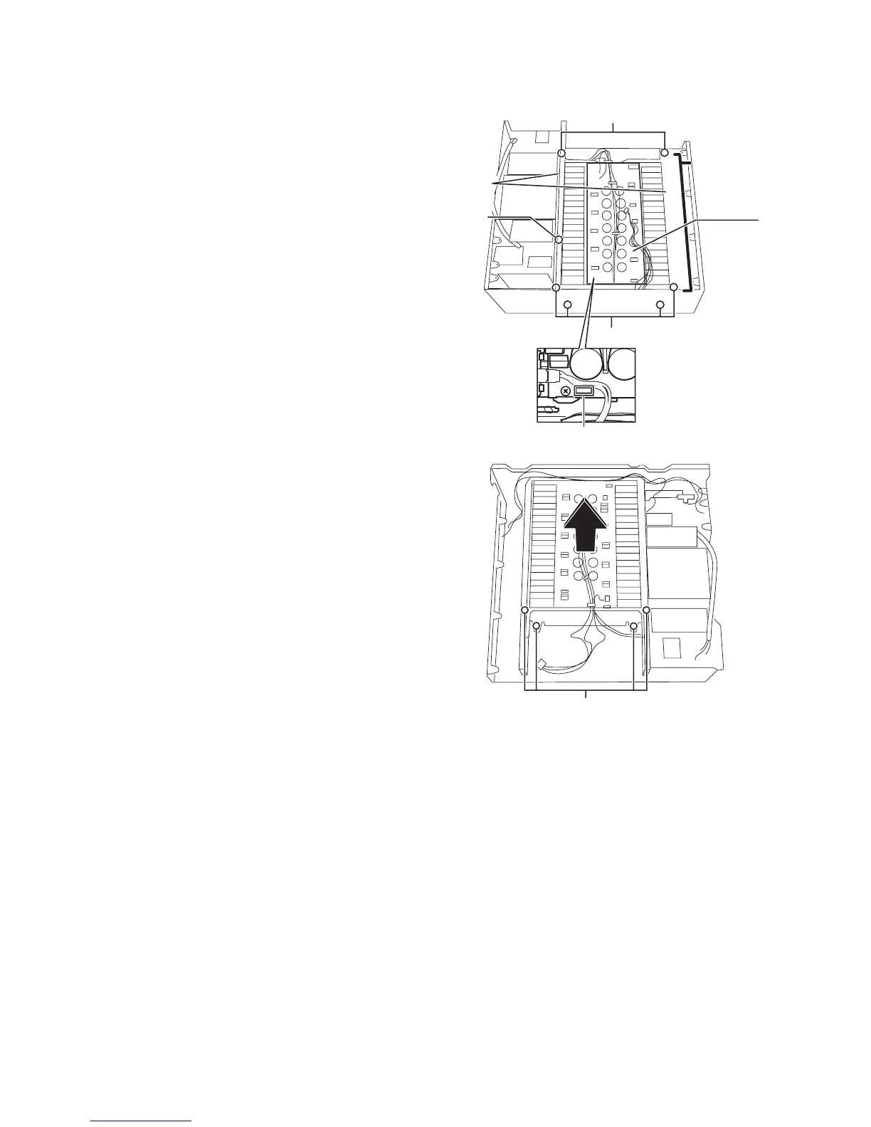
3.1.21 Removing the power amp. Assembly
(See Fig.20 and 21)
• Prior to performing the following procedures, remove the top
cover, rear panel, front panel assembly, system control board,
DSP board, audio signal 1 board, audio signal 2 board, video
board, S video board, V compo 1 board and speaker board.
(1) Remove the three screws Q fixing the barriers, and remove
the tow barriers.
(2) Remove the eight screws R attaching the power amp. as-
sembly.
(3) Pull up the power amp. assembly.
Fig.20
Fig.21
(Front side)
Q
Q
R
Power
amp.
assembly
Power amp.
board
Barrier
CN738
R
(Rear side)