(No.YA068)1-9
3.1.4 REMOVING THE SLOT HOLDER AND SLOT PWB
• Remove the TOP COVER.
• Remove the REAR PANEL.
• Remove the TERMINAL BRACKET.
(1) Detach the connector connected SLOT PWB and SIGNAL
PWB, then remove the SLOT PWB with SLOT HOLDER.
(2) Remove the 4 screws [R] as shown in Fig.4.
(3) Then remove the SLOT PWB from SLOT HOLDER.
3.1.5 REMOVING THE CHASSIS BASE
• Remove the TOP COVER.
• Remove the REAR PANEL.
• Remove the TERMINAL BRACKET.
(1) Fall the unit down side ways as able to see the bottom side.
(2) Lift the back side of the CHASSIS BASE slightly, and
separate it from BOTTOM COVER.
(3) Raise the 2 claws positioned bottom of the CHASSIS
BASE, and detach the CHASSIS BASE from BOTTOM
COVER.
(4) Then pull the CHASSIS BASE out to rearward.
3.1.6 REMOVING THE BOTTOM COVER
• Remove the TOP COVER.
• Remove the REAR PANEL.
• Remove the TERMINAL BRACKET.
• Remove the CHASSIS BASE.
(1) Set the CRT front surface downward, and stand the bottom
cover to facing it toward you.
At this time, care must be exercised not to damage the front
panel and CRT surface.
(2) Remove the 4 screws [N] as shown in Fig.4.
(3) Remove the 2 screws [P] as shown in Fig.4.
(4) While spreading the BOTTOM COVER to the bottom side,
pull it out to rearward to remove it.
3.1.7 REMOVING THE SPEAKER
• Remove the TOP COVER.
(1) Slightly spread the claws of the speaker holder.
(2) Pull up the SPEAKER to remove it.
3.1.8 CHECKING THE PW BOARD
To check the PW board from back side.
(1) As shown in Fig.5, place the unit for service.
(2) Erect the chassis base vertically so that you can easily
check the PW board from back side.
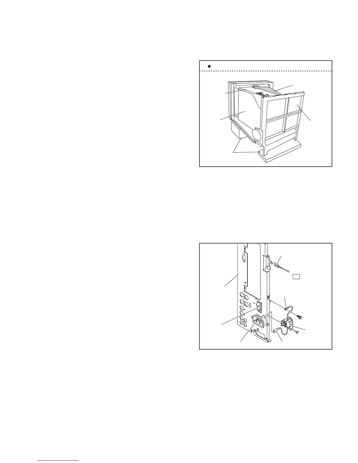
Fig.5
CAUTION
• Before turning on power, make sure that the earth wire
properly connected to the TERMINAL BRACKET, which is
attached the main power switch and AC inlet. (Fig.6)
• And make sure that the CRT earth wire and the other
connectors are properly connected.
• When erecting the CHASSIS BASE, be careful so that there
will be no contacting with the other PW board.
• Be careful while erecting the PW board, because easily fall
down.
Fig.6
3.1.9 WIRE CLAMPING AND CABLE TYING
(1) Be sure to clamp the wire.
(2) Never remove the cable tie used for tying the wires
together.
Should it be inadvertently removed, be sure to tie the wires
with a new cable tie.
MAIN PWB
SIGNAL
PWB
TERMINAL
BRACKET
INSULATOR
(Card Board etc.)
STAND
Example of placement for SERVICE
TO MAIN PWB
( E2 )
AC INLET
TERMINAL
BRACKET
PLUG
EARTH WIRE
LUG
EARTH PLUG
POWER SW.
CORE
FILTER