(No.YA068)1-7
SECTION 3
DISASSEMBLY
3.1 DISASSEMBLY PROCEDURE
CAUTION
Even if the power switch is turned off, some parts in this unit
are alive. Be sure to disconnect the power plug from the AC
outlet before disassembly and reassembly.
3.1.1 REMOVING THE TOP COVER
(1) Remove the 8 screws [A] as shown in Fig.4.
(2) Slightly spread the bottom of the TOP COVER
(3) Shift the TOP COVER rearward and raise it upward to
remove it.
3.1.2 REMOVING THE REAR PANEL
• Remove the TOP COVER.
(1) Remove the 8 screws [B] as shown in Fig.4.
(2) Remove the 1 screw [C] as shown in Fig.4.
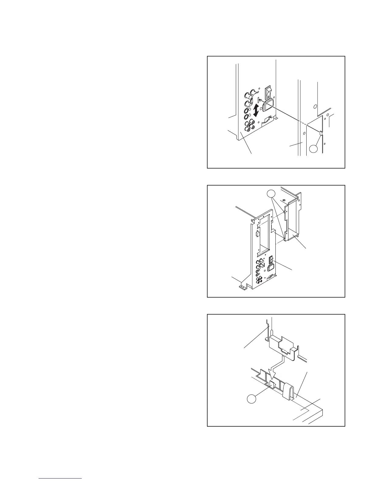
(3) As shown in Fig.1, lift the rear panel and remove the claw
[K] from the terminal bracket.
(4) Shift the top portion of the REAR PANEL slightly rearward
and raise it upward to remove it.
3.1.3 REMOVING THE TERMINAL BRACKET
• Remove the TOP COVER.
• Remove the REAR PANEL.
(1) Remove the 1 screw [D] as shown in Fig.4.
(2) Remove the 5 screw [E] as shown in Fig.4.
(3) Remove the 1 screws [F] and [G] as shown in Fig.4.
(4) Remove the 1screw [H] as shown in Fig.4.
(5) Remove the 2 hexagonal screws [J] as shown in Fig.4.
(6) Pull the PW connector out from the MAIN PWB, connected
between the MAIN POWER SWITCH and MAIN PWB.
(7) As shown in Fig.2, lift the SLOT HOLDER slightly, and
remove the 2 claws [L] attached SLOT HOLDER with the
TERMINAL BRACKET.
(8) As shown in Fig.3, raise the claw [M] positioned back side
of the CHASSIS BASE, and lift the TERMINAL BRACKET
from the CHASSIS BASE.
(9) Slightly shift the TERMINAL BRACKET rearward and raise
it upward to remove it.
Fig.1
Fig.2
Fig.3
K
REAR PANEL
TERMINAL BRACKET
TERMINAL BRACKET
SLOT HOLDER
L
TERMINAL BRACKET
CHASSIS BASE
MAIN PWB
M