1-38 (No.YA068)
SECTION 5
TROUBLE SHOOTING
5.1 OUTLINE
This model includes a SELF DIAGNOSIS FUNCTION that checks the circuit operating status and in event of malfunction, displays
and stores the data in a memory. The data are stored in memory.
Fault detection starts with the I
2
C bus and is performed according to the input states of the control lines connected to the MAIN CPU.
5.2 USAGE
5.2.1 SELF DIAGNOSIS FUNCTION MODE ENTRY
(1) While press the [MENU] button and [CONTRAST/BRIGHT]
button simultaneously, and push the POWER switch to turn
on.
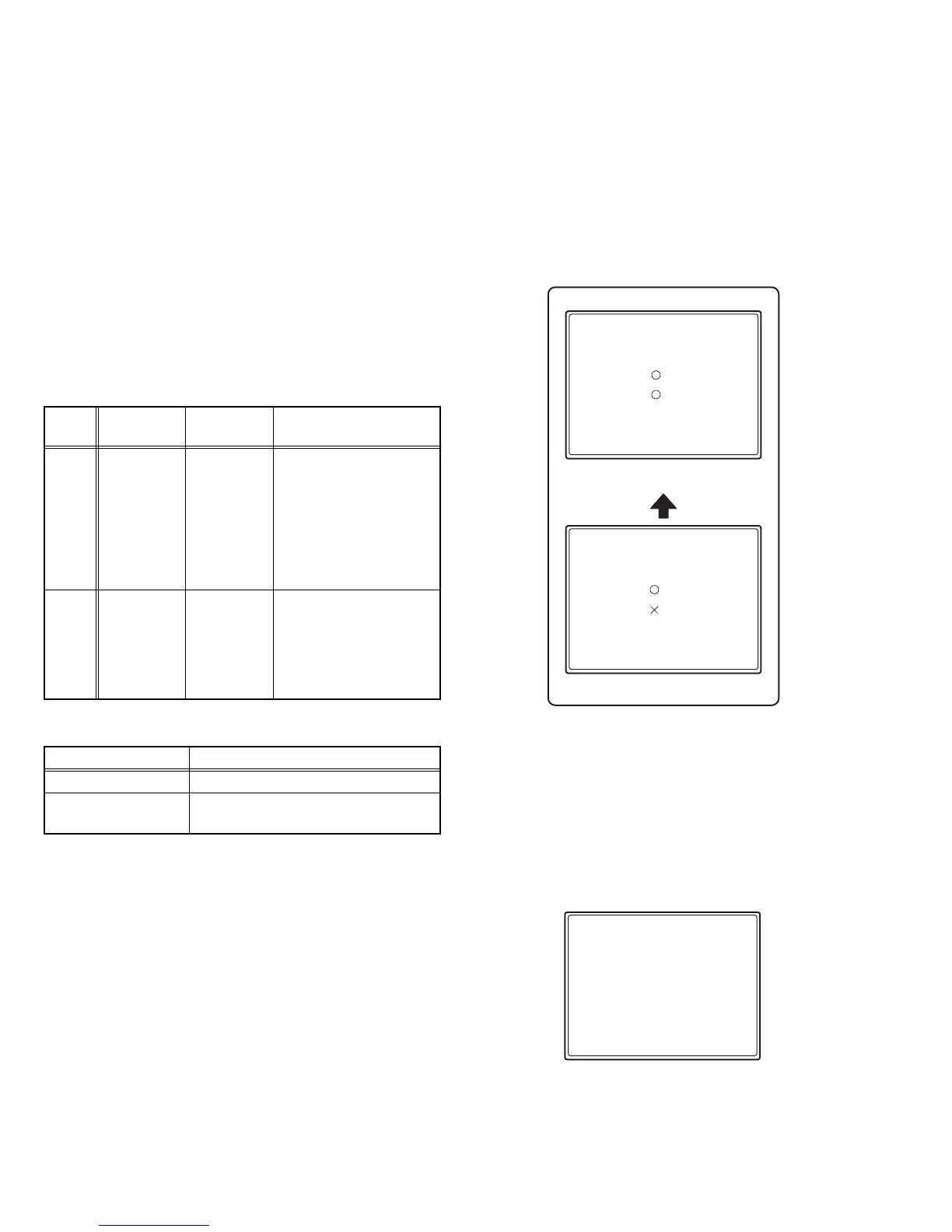
(2) Then displays the SELF-DIAGNOSIS FUNCTION screen.
Make sure all items of this MENU are "O" (Fig.1).
(3) If "X" is in items (Fig.2), press the [MENU] button and
[VOLUME /SELECT - (DOWN)] button at same time.
5.2.2 CONTENTS
• If in event malfunction at RASTER not display, at this time
POWER LED flashes.
5.2.3 SELF DIAGNOSIS FUNCTION MODE RELEASE
Turn the POWER switch off or disconnect the power plug from
AC outlet. In this way, not to clear the error counts.
5.2.4 RESET THE ERROR COUNT
(1) While press the [MENU] button and [CHROMA/PHASE]
button simultaneously, and push the MAIN POWER switch
on.
(2) Then displays the screen as shown in Fig.3. Press the [ + ]
key. Then clear the error count of the each item.
5.2.5 FAULT HISTORY
The fault history counts up to a maximum of 9 times for each
item. If the number of times exceeds 9, the display remains at 9.
The fault history remains stored in the memory until deleted.
Check
item
Detected
contents
Detection
method
Cause
B1
The over-
current of B1
line is
checked and
vertical
oscillation is
checked.
It will be
detect the
B1-PRO port
in IC6701
51-pin on
SIGNAL
PWB.
Destruction of a level
oscillation transistor
Q1521 on MAIN PWB can
be considered.
Vertical oscillation
Destruction of a vertical
out IC1401 on MAIN PWB
can be considered.
X-RAY
The unusual
rise of CRT
anode
voltage is
checked.
IC6701 50-
pin on
SIGNAL
PWB
Destruction of a
resonance capacitor
(C2521, C2522, C2528)
on SUB DEF PWB or FBT
T1551 on MAIN PWB can
be considered.
Cause Led flashing cycle
X-RAY PROTECTION Quickly (0.1 sec on / 0.1 sec off cycles)
B1 OVER CURRENT
PROTECTION
Slowly (1.0 sec on / 1.0 sec off cycles)
PROTECTOR
B1
:
X-RAY
:
Fig.1
Fig.2
PROTECTOR
B1
1
:
X-RAY
:
SELF DIAGNOSIS RESET
<SET-UP MENU> RESET
Are you sure?
"Yes" then <+>
"No" then <MENU>
Fig.3
0
0
+
0
X