1-8 (No.MB066)
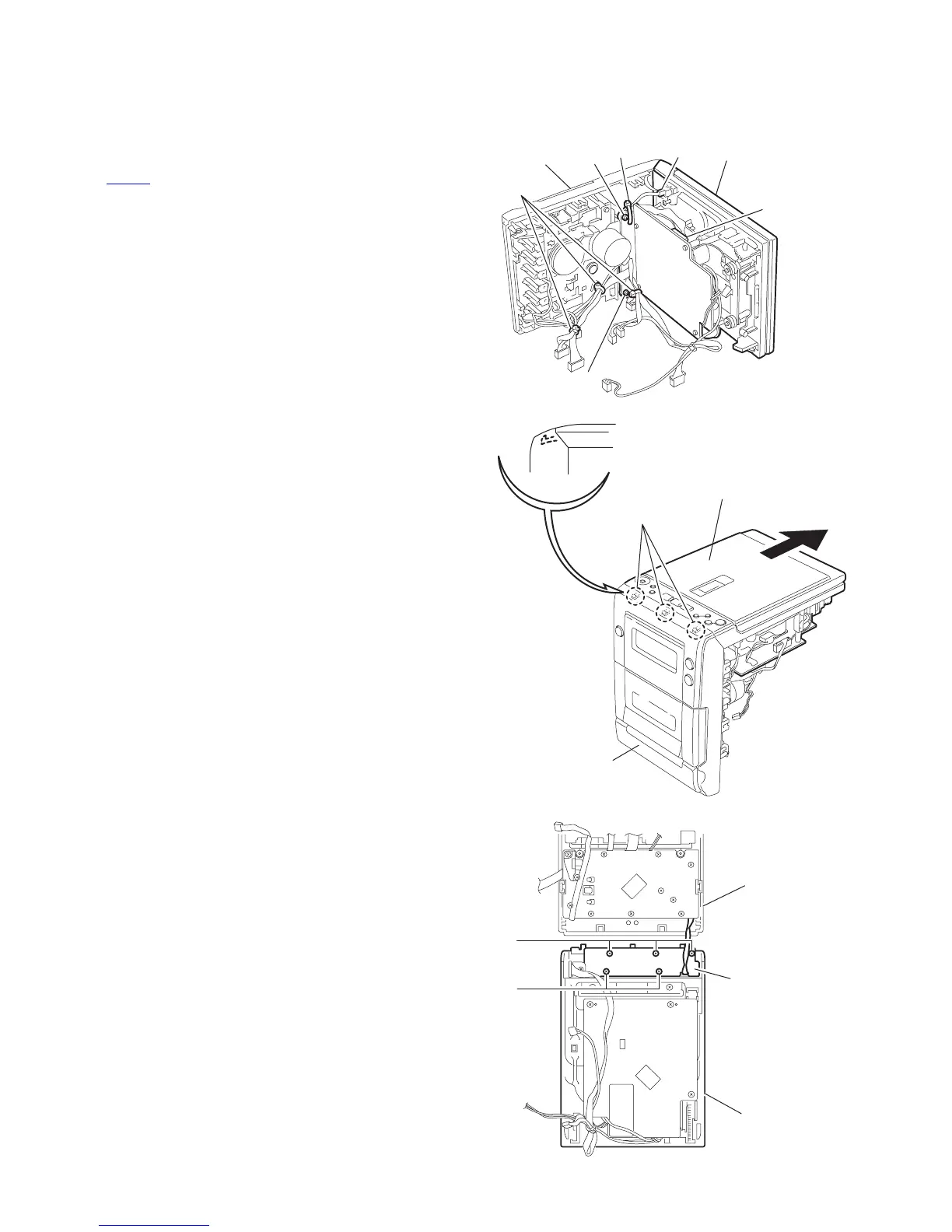
3.1.3 Removing the CD mechanism assembly and the Switch board
(See Fig.8 ~ 10)
• Prior to performing the following procedure, remove the front
panel assembly and the main board.
(1) Cut off the four bands setting the wires.
(2) Disconnect the wire from connector on the CD open switch
and CN705
on the CD mechanism board.
(3) Remove the two screws F on the front panel assembly.
(4) Release the joint d of the CD mechanism assembly.
(5) Remove the five screws G attaching the switch board to the
CD mechanism assembly.
Fig.8
Fig.9
Fig.10
Band
F
F
Band
CN705
Open switch
connecter
CD mechanism
assembly
Front panel
assembly
Joint d
CD mechanism
assembly
Front panel assembly
G
G
Switch board
CD mechanism
assembly
Front panel
assembly
 Loading...