XV-SA600BK/XV-SA602SL
10
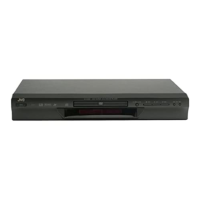
2.2.3 Removing the traverse mechanism
assembly (See Fig.2-11 and 2-12)
• Prior to performing the following procedure, remove
the clamper assembly and the tray.
(1) Remove the four screws B attaching the traverse
mechanism assembly.
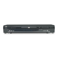
ATTENTION:
Before reattaching the traverse
mechanism assembly, pass the card
wire extending from the spindle motor
board through the notch d of the elevator.
Fig.2-11
Fig.2-12
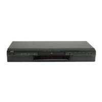
2.2.4 Removing the elevator (See Fig.2-13)
• Prior to performing the following procedure, remove
the clamper assembly, the tray and the traverse
mechanism assembly.
(1) Extend each bar e inside of the loading base
outward and detach the elevator shaft.
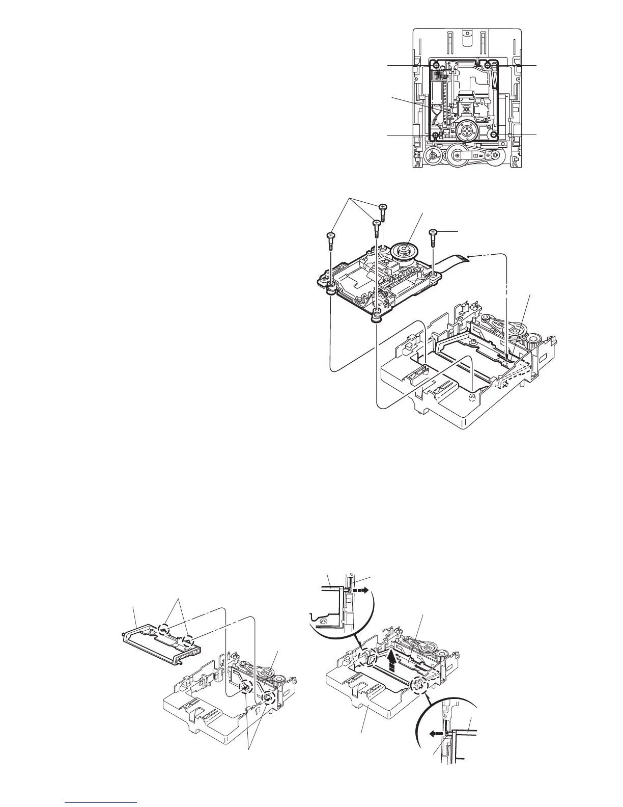
ATTENTION:
When reattaching, first fit the two shafts on the
front of the elevator to the slots f of the slide cam.
Fig.2-13
B
B
raverse mechanism
ssembly
BB
Traverse mechanism assembly
Elevato
Notch d
Elevator
Elevat
e
e
Loading base
levator
Shafts
Slide cam
Slots f
 Loading...