XV-SA600BK/XV-SA602SL
15
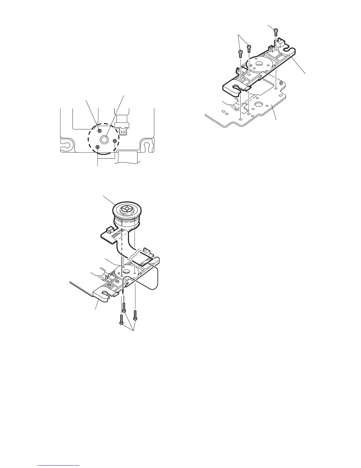
2.3.5 Removing the spindle motor assembly
(See Fig.2-26 to 2-28)
(1) Remove the three screws L attaching the spindle motor on
the bottom of the mechanism base.
ATTENTION:
When reattaching, pass the card wire extending
from the spindle motor board through the notch
of the spindle base.
(2) Remove the three screws M attaching the spindle base.
Fig.2-26
Fig.2-27
Fig.2-28
L
L
Spindle base
L
M
Spindle bas
Mechanism base
 Loading...