EN
Description
KACO Operating Instructions blueplanet . TL - . TL Page
Description
. Mode of Operation
The inverter converts the DC voltage generated by the PV modules into AC voltage and feeds it into the grid. The
starting procedure begins when there is sucient sunlight and a specic minimum voltage is present in the inverter.
The feed-in process begins once the PV generator has passed the insulation test and the grid parameters are within
the requirements imposed by the grid operator for a specic monitoring time. If, as it gets dark, the voltage drops
below the minimum voltage value, feed-in operation ends and the inverter switches o.
. Diagram
1
2
5
4
3
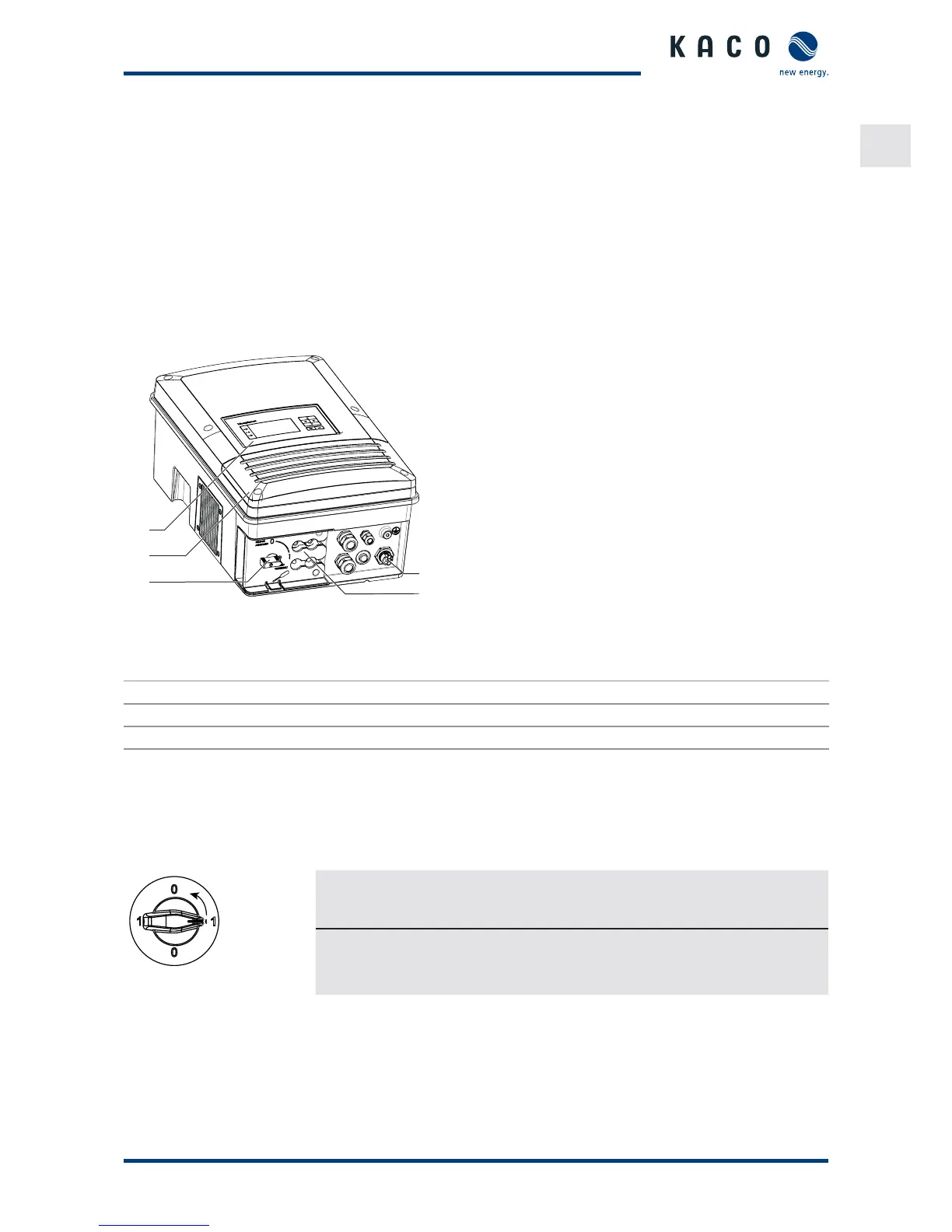
Figure : Inverter diagram
Key
1 Control panel 4 DC connection (DC connector)
2 Cover for the connection area 5 AC connection (5-pole connecting plug)
3 DC isolator switch
.. Mechanical components
DC isolator switch
The DC isolator switch is located on the underside of the inverter. The DC isolator switch is used to disconnect the
inverter from the PV generator in order to carry out service.
Figure : DC isolator switch
Disconnecting the inverter from the PV generator
" Switch the DC isolator switches from (ON) to (OFF).
Connecting the inverter to the PV generator
" Switch the DC isolator switches from (OFF) to (ON).
.. Electrical functions
A potential-free relay contact is integrated in the inverter. Use this contact for one of the following functions:
Fault signal relay
The potential-free relay contact closes as soon as there is a fault during operation. You use this function, for example,
to signal a fault visually or acoustically.

 Loading...