OPERATION MANUAL
AF INTEGRA / AF-H INTEGRA ELT
PAGE: 106
JUN 20/2013
stopped after 24 hours to extend the 121.5 MHz transmission for as long as
possible.
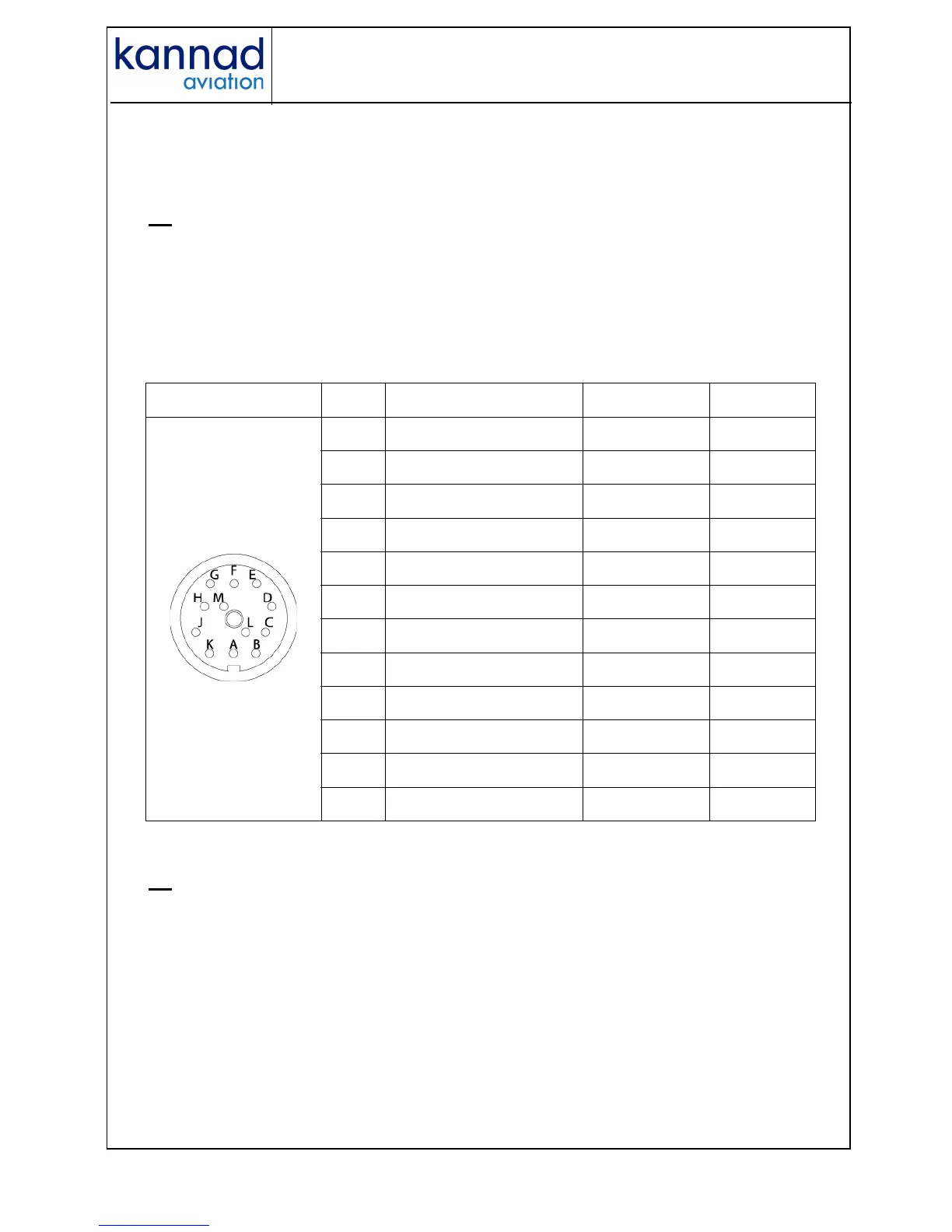
G. Electrical interfaces
J1
DIN 12 socket J1 is dedicated for connection to an optional Remote Control
Panel, to a Programming or Maintenance Dongles or to a programming
equipment (PR600).
IMPORTANT: Shielded cables are recommended. The required wires
are AWG24.
Table 1: J1 connector pin-out
J2
BNC female connector J2 is used to connect the external antenna through a
50 Ω coaxial cable.
IMPORTANT NOTICE:
The use of a low attenuation coaxial cable is recommended. The
maximum permitted attenuation in the coaxial is 1db@400 MHz.
J1 PIN Signal Name Destination Direction
Viewed from
Front Face
J1-A RCP RESET RCP IN
J1-B DONGLE RX SMM / PGM IN
J1-C DONGLE CS SMM OUT
J1-D DONGLE SK SMM OUT
J1-E DONGLE TX SMM / PGM OUT
J1-F DONGLE ALE2P SMM OUT
J1-G RCP COMMON RCP OUT
J1-H RCP BUZZER RCP OUT
J1-J RCP LED RCP OUT
J1-K RCP ON RCP OUT
J1-L DONGLE GND SMM / PGM OUT
J1-M RCP 2W COMMON RCP OUT