OPERATION MANUAL
AF INTEGRA / AF-H INTEGRA ELT
PAGE: 206
JUN 20/2013
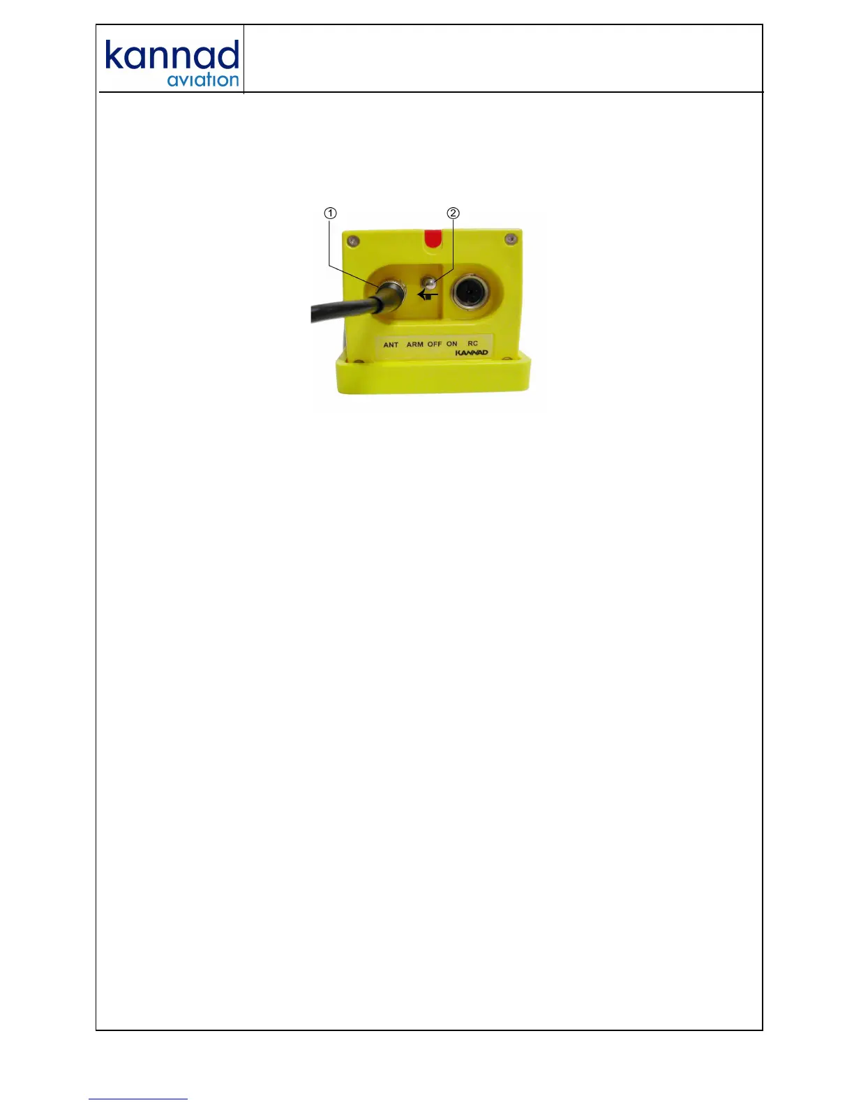
4. ELT transmitter Connection
1. Connect the cable of the outside antenna to the BNC connector of the
front panel.
2. Set the 3-position switch of the front panel to ARM.
Figure 3: Installation, controls and connectors
• Perform the first power up procedure (see below).
5. First power up
Perform the following tests:
1. ELT operational tests:
• connect the external antenna to J2;
• switch the ELT from OFF to ARM;
• check that the Self-Test result is OK (one long flash).
2. 406 & 121.5 MHz transmission tests (optional):
Refer to Section B. Test of transmitted signals page 302.
At the end of the first power up procedure, switch the ELT to ARM.
The ELT is now in stand by mode and ready to be activated:
• either automatically by G-Switch sensor if a crash occurs;
• or manually by an optional Remote Control Panel (when connected).
Note : switching to ON directly on the ELT front panel will also
activate the ELT.